Double-support elastic driving type cable coiling block

A cable reel, driven technology, applied in the field of mobile energy supply devices, can solve the problems of occupying a large installation space, thin installation form, insufficient stability, etc., achieving strong installation stability, low production cost, and saving installation space. Effect

Pending Publication Date: 2017-11-07
YUEYANG HAIRUN ELECTRIC
View PDF7 Cites 2 Cited by
  • Summary
  • Abstract
  • Description
  • Claims
  • Application Information

AI Technical Summary

Problems solved by technology

[0002] Most of the currently used elastic drive cable reels are installed with a single fulcrum flange or with an L-shaped single support. This installation is more suitable for cables with a smaller outer diameter and lighter weight. When the outer diameter of the cable is large and the weight is large, that is, when the torque load of the reel is large, this installation form is thin and the stability is not enough.
There are also double-support installation methods for stability. Because the mainspring spring used as the driving force of the existing elastic-driven cable reel is externally installed, it is installed on one end of the reel, and the collector is installed on the other end of the reel. Although the stability is enhanced, but due to the large axial dimension, it needs to occupy a large installation space
In addition, the reel of the elastic-driven cable reel generally adopts an integral welded structure, and its production cost is relatively high.

Method used


Image

  • Double-support elastic driving type cable coiling block
  • Double-support elastic driving type cable coiling block
  • Double-support elastic driving type cable coiling block

Examples


Embodiment Construction

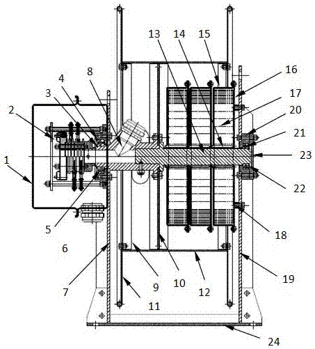
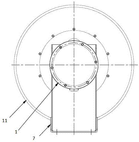
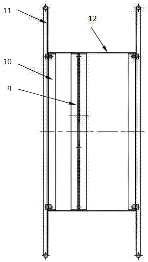
[0022] Depend on Figure 1~3 It can be seen that the present invention is a double-support elastically driven cable reel, which includes a collector cover 1, a collector 2, a shaft retaining ring 3, a hole retaining ring 4, a bearing 5, an electrical bearing seat 6, an electrical Side bracket 7, Denso half shaft 8, Dragon slip ring 1 9, Keel ring 2 10, End plate 11, Rolling cylinder 12, Spring half shaft 13, Spring inner sleeve 14, Spring box 15, Spring box cover 16 , clockwork spring 17, locking stud 18, spring side bracket 19, spring side bearing seat 20, bearing 21, shaft retaining ring 22, bearing gland 23, mounting base plate 24, and some bolts, nuts, set screws .

[0023] The central shaft of the cable reel includes an electrical installation semi-axis 8 and a spring semi-axis 13; The stop ring 3, the stop ring 4 limit for the hole;

[0024] The electric assembly half shaft 8 and the spring half shaft 13 are rigidly connected by set screws.

[0025] Depend on Figur...


PUM


Abstract

The invention discloses a double-support elastic driving type cable coiling block. The double-support elastic driving type cable coiling block comprises an electric fitting half shaft, a spring half shaft, a clockwork spring, a stand and a reel and is characterized in that a center shaft of the double-support elastic driving type cable coiling block comprises the electric fitting half shaft and the spring half shaft, and the electric fitting half shaft is arranged on an electric fitting side support along with an electric fitting side bearing block and a bearing; the spring half shaft is arranged on a spring side support along with a spring side bearing block and a bearing; the electric fitting half shaft and the spring half shaft are in rigidity connection; the reel is arranged on the center shaft formed through connection of the electric fitting half shaft and the spring half shaft; and the clockwork spring is arranged in the spring half shaft arranged in a coiling block body. Due to adoption of the double supports, the installing stability of the elastic driving type cable coiling block is high; the clockwork spring is arranged in the reel, the axial size is reduced, the installing space is saved, and accordingly the occupied installing space is small; and the reel is assembled and integrated, spot welding combination is adopted between a keel ring and the coiling block body, and accordingly the production cost is low.

Description

technical field [0001] The invention relates to a mobile energy supply device, in particular to an elastic force driven cable reel. technical background [0002] Most of the currently used elastic drive cable reels are installed with a single fulcrum flange or with an L-shaped single support. This installation is more suitable for cables with a smaller outer diameter and lighter weight. When the outer diameter of the cable is large and the weight is large, that is, when the torque load of the reel is large, this installation form is thin and the stability is not enough. There are also double-support installation methods for stability. Because the mainspring spring used as the driving force of the existing elastic-driven cable reel is externally installed, it is installed on one end of the reel, and the collector is installed on the other end of the reel. Although the stability is enhanced, due to the large axial dimension, it needs to occupy a large installation space. In ...

Claims


Application Information

Patent Timeline
Patent Type & Authority Applications(China)
IPC IPC(8): B65H75/18B65H75/14
CPCB65H75/14B65H75/18B65H2701/34
Inventor 杨大林陈世华符建光刘剑刘彬
Owner YUEYANG HAIRUN ELECTRIC
Why Eureka
Try Eureka