

Ingot casting furnace capable of improving average conversion efficiency of silicon ingot
A technology of conversion efficiency and ingot casting furnace, which is applied in the direction of polycrystalline material growth, crystal growth, single crystal growth, etc., can solve the uneven temperature distribution of the thermal field at the corner, affect the average conversion efficiency of silicon ingots, and affect the dispersion of silicon ingot efficiency To improve the average conversion efficiency, improve the competitiveness of use, and improve the dispersion
- Summary
- Abstract
- Description
- Claims
- Application Information
AI Technical Summary
Problems solved by technology
Method used
Image

Examples
Embodiment Construction
[0023] The present invention will be described in detail below in conjunction with the accompanying drawings and embodiments.
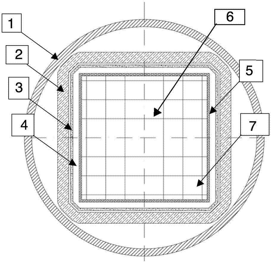
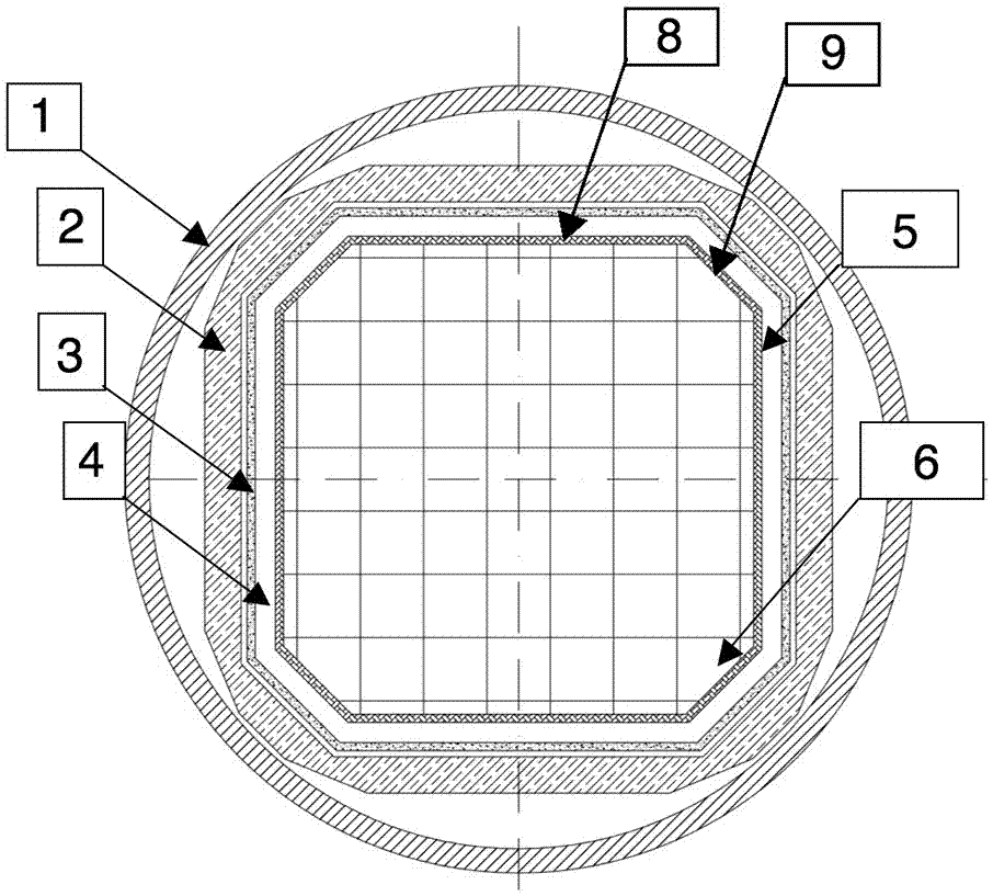
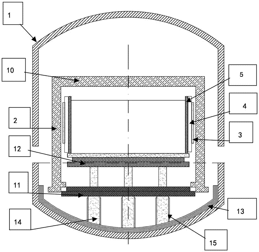
[0024] Such as Figure 2-5 Shown: this embodiment is a kind of ingot casting furnace that improves the average conversion efficiency of silicon ingot, comprises furnace body 1 and is arranged on the crucible 5 inside furnace body 1, and the crucible 5 in the present embodiment is quartz material, and silicon ingot 6 is positioned at In the crucible 5, a graphite column 14 is vertically arranged at the bottom inside the furnace body 1, and a heat exchange platform 12 is arranged horizontally on the top of the graphite column 14. The crucible 5 is placed on the heat exchange platform 12, and the heat exchange platform 12 mainly plays a role in heat conduction. role, between the periphery of the crucible 5 and the inner wall of the furnace body 1, a graphite shield layer 4, a heater layer 3 and a heat preservation cover layer 2 are arranged successively....
PUM
 Abstract
Description
Claims
Application Information