Achievement method for predicting laser welding deformation

A technology of laser welding and realization method, which is applied in welding equipment, auxiliary welding equipment, welding/cutting auxiliary equipment, etc., can solve the problem of inability to accurately fit the morphology of the molten pool area at the weld and control the morphology of the weld pool area of ​​the weld. , Welding deformation simulation effect is poor, etc.

Inactive Publication Date: 2017-11-07
SHANGHAI JIAO TONG UNIV
View PDF3 Cites 10 Cited by
  • Summary
  • Abstract
  • Description
  • Claims
  • Application Information

AI Technical Summary

Problems solved by technology

[0003] The present invention aims at the defect that the existing technology cannot control the shape of the molten pool area of ​​the weld seam by defining the wire grid profile, cannot accurately fit the shape of the molten pool area at the weld seam, and has poor welding deformat

Method used


Image

  • Achievement method for predicting laser welding deformation
  • Achievement method for predicting laser welding deformation
  • Achievement method for predicting laser welding deformation

Examples


Embodiment Construction

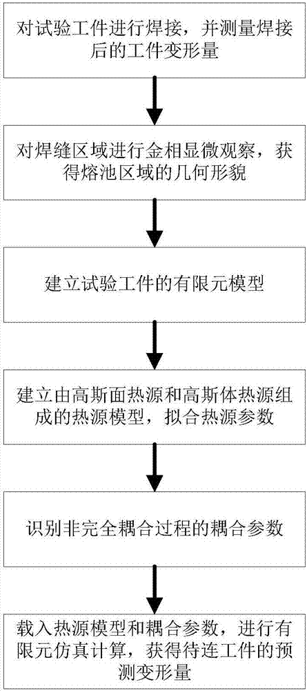
[0038] Such as figure 1 As shown, this embodiment includes the following steps:

[0039] 1) Weld the test workpiece and measure the deformation of the workpiece after welding.

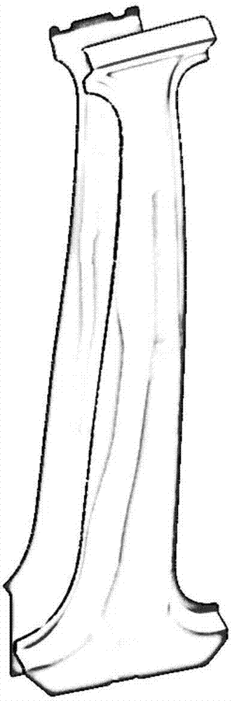
[0040] Such as figure 2 As shown, the test workpiece is the B-pillar area panel in the automobile body, that is, the laser welding method is used to weld the B-pillar inner panel and the B-pillar reinforcement. The reinforced version of the B-pillar and the inner panel of the B-pillar are the test workpieces. The test workpiece is optically scanned to obtain the geometric shape of the test workpiece, which is used to establish the finite element model of the test workpiece.

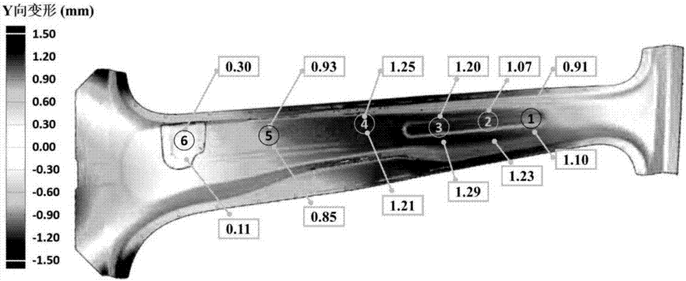
[0041] Such as image 3 As shown, after the test workpiece is welded, three-dimensional optical scanning is carried out to obtain the deformation of the test workpiece after welding.

[0042] 2) Conduct metallographic microscopic observation of the weld area to obtain the geometric morphology of the molten pool area.

[004...


PUM


Abstract

Provided is an achievement method for predicting laser welding deformation. The geometrical morphology of a weld pool zone after welding is acquired, a finite element model and a heat source three-dimension scanning model consisting of a Gaussian surface heat source and a Gaussian body heat source are established, then heat source parameters are fit, coupling parameters in the non-complete coupling process are identified, a finite element model of a workpiece to be connected in production is established, the heat source three-dimension scanning model and the coupling parameters are loaded, finite element simulating calculation is performed, and finally the predicted deformation of the workpiece to be connected is obtained. The accuracy of temperature field calculation is improved, the accuracy of deformation prediction is improved, and the prediction time of the welding deformation is greatly shortened.

Description

technical field [0001] The invention relates to a technology in the field of laser welding, in particular to a method for realizing the prediction of laser welding deformation. Background technique [0002] The laser welding process has gradually begun to be widely used in the joining process of automobile body panels. It has the advantages of high automation, fast welding speed, deep welding penetration, and high joint strength, but it is also accompanied by problems such as welding deformation and residual stress. The deformation caused by laser welding often exceeds the assembly tolerance of the body panel, which has a great influence on the assembly accuracy. Contents of the invention [0003] The present invention aims at the defect that the existing technology cannot control the shape of the molten pool area of ​​the weld seam by defining the wire grid profile, cannot accurately fit the shape of the molten pool area at the weld seam, and has poor welding deformation ...

Claims


Application Information

Patent Timeline
IPC IPC(8): G06F17/50B23K37/00
CPCB23K37/00G06F30/23
Inventor 刘钊王庆朱平
Owner SHANGHAI JIAO TONG UNIV
Why Eureka
Try Eureka