
Device for generating multimodal orbital angular momentum of mechanical reconfigurable array antennas and method thereof

An orbital angular momentum, array antenna technology, applied in antennas, antenna arrays, antenna combinations with different interactions, etc., can solve the problems of complex design process, limited wide application, complex feeding network, etc., to achieve the effect of simplifying the structure

Inactive Publication Date: 2017-11-07
XIDIAN UNIV
View PDF7 Cites 18 Cited by
  • Summary
  • Abstract
  • Description
  • Claims
  • Application Information

AI Technical Summary

Problems solved by technology

Although the form of the array element is not limited and the array arrangement is flexible, this method needs to redesign the array element structure and arrangement when generating orbital angular momentum of different modes, which makes the design process complicated.
[0007] To sum up, in the existing technologies for generating orbital angular momentum with array antennas, one device can only generate orbital angular momentum of one mode, and the feeding network is complex. To generate orbital angular momentum of different modes, it is necessary to redesign the array antenna. The element structure and arrangement method have the problem of complex design process, which limits the wide application of this technology in the microwave frequency band

Method used


Image

  • Device for generating multimodal orbital angular momentum of mechanical reconfigurable array antennas and method thereof
  • Device for generating multimodal orbital angular momentum of mechanical reconfigurable array antennas and method thereof
  • Device for generating multimodal orbital angular momentum of mechanical reconfigurable array antennas and method thereof

Examples


Embodiment 1

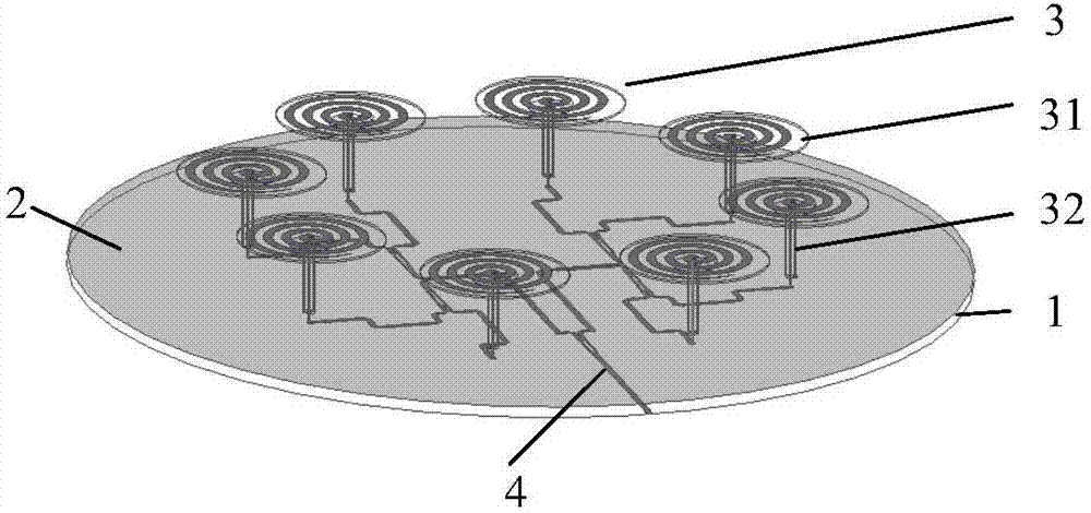
[0040] refer to figure 1 , a device for generating multi-mode orbital angular momentum by a mechanically reconfigurable array antenna, including a first dielectric substrate 1 , a first metal floor 2 , a single-arm helical antenna unit 3 and a microstrip power divider 4 . The first dielectric substrate 1 adopts a dielectric constant of 2.65 and a radius L 1 For a circular dielectric material of 200mm, its thickness h 1 is 1 mm; a first metal floor 2 is printed on the upper surface of the first dielectric substrate 1, and the shape and size of the first metal floor 2 are the same as that of the first dielectric substrate 1; =8 single-arm helical antenna units 3, wherein, the N=8 single-arm helical antenna units 3 are located on the same horizontal plane with a height S of 35mm from the first metal floor 2, and along the radius R 1 Circumferential arrangement of 120 mm forms a ring structure, and the axis of the ring structure coincides with the axis of the first dielectric su...

Embodiment 2

[0061] Embodiment 2 has the same structure as Embodiment 1, only the following parameters are adjusted.

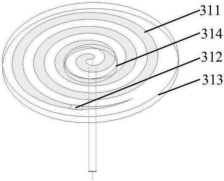
[0062] The number of single-arm helical antenna units N=4, the radius R of the ring structure 1 =80mm, the number of turns t=3 of the microstrip spiral arm 311, the resistance value Z=140Ω of the resistor 312, and the radius of the second dielectric substrate 313 is R 2 = 25mm.

Embodiment 3

[0064] Embodiment 3 has the same structure as Embodiment 1, only the following parameters are adjusted.

[0065] The number of single-arm helical antenna units N=14, the R of the ring structure 1 =140mm, the number of turns t=4 of the microstrip spiral arm 311, the resistance value Z=180Ω of the resistor 312, and the radius of the second dielectric substrate 313 is R 2 =48mm.

[0066] Below in conjunction with simulation experiment, technical effect of the present invention is further illustrated:

[0067] 1. Simulation conditions and content:

[0068] Utilize Ansys HFSS software to carry out simulation calculation to the S parameter of embodiment 1 in the scope of 2-5GHz, the result is as follows Figure 4 shown.

[0069] Utilize Ansys HFSS software to carry out simulation calculation to the axial ratio AR of embodiment 1 in the range of 2-5GHz, the result is as follows Figure 5 shown.

[0070] Utilize Ansys HFSS software to simulate the mode l=1 far-field three-dimens...


PUM

PropertyMeasurementUnit
Thicknessaaaaaaaaaa
Radiusaaaaaaaaaa
Resistanceaaaaaaaaaa

Abstract

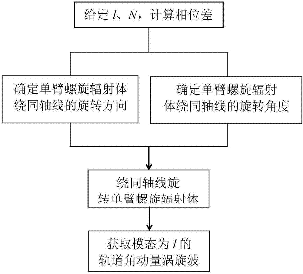
The invention provides a device for generating multimodal orbital angular momentum of mechanical reconfigurable array antennas and method thereof, and aims at realizing the mechanical reconfigurable characteristic of the generation device and generating the multimodal orbital angular momentum. The generation device comprises a feed network which is composed of a first dielectric substrate, a first metal ground plate and a microstrip power divider and array antennas formed by single-arm spiral antenna units which are arranged along a ring structure, wherein the single-arm spiral radiators can rotate around the lower coaxial line so as to realize the phase compensation characteristic of the multimodal orbital angular momentum. An electric signal is transmitted to each single-arm spiral radiator through the input end and all the output ends of the microstrip power divider and the coaxial line connected with all the output ends, and the single-arm spiral radiators rotate different angles along different directions to provide different amount of phase compensation to the electric signal to generate different modes of orbital angular momentum vortex beams so as to realize the mechanical reconfigurable characteristic. The device and the method can be used for information transmitting and receiving in the communication technology.

Description

technical field [0001] The invention belongs to the technical field of wireless communication, and particularly relates to a device and method for generating multi-mode orbital angular momentum electromagnetic vortex waves by a mechanically reconfigurable array antenna, which can be used in radio frequency and microwave bands. Background technique [0002] Due to the popularity of mobile smart terminals and the rapid development of related data service technologies, the demand for wireless services has shown explosive growth. However, the limitedness, exclusivity and scarcity of wireless spectrum resources have greatly restricted the development of wireless communication technology. For this reason, time division multiple access (TDMA), code division multiple access (CDMA), Various multiplexing techniques such as (OFDM) are used to improve the utilization rate of wireless spectrum. However, wireless communication technology since the Marconi era has been mainly using the li...

Claims


Application Information

Patent Timeline
IPC IPC(8): H01Q1/38H01Q3/32H01Q21/29
CPCH01Q1/38H01Q3/32H01Q21/293
Inventor 李龙周潇潇刘海霞
Owner XIDIAN UNIV
Learn More