Multifunctional mouse tail intravenous injection platform
A multi-functional, rat-tailed technology, applied in the field of medical devices, to achieve the effect of reducing labor costs, precise control, and ingenious design
- Summary
- Abstract
- Description
- Claims
- Application Information
AI Technical Summary
Problems solved by technology
Method used
Image
Examples
Embodiment 1
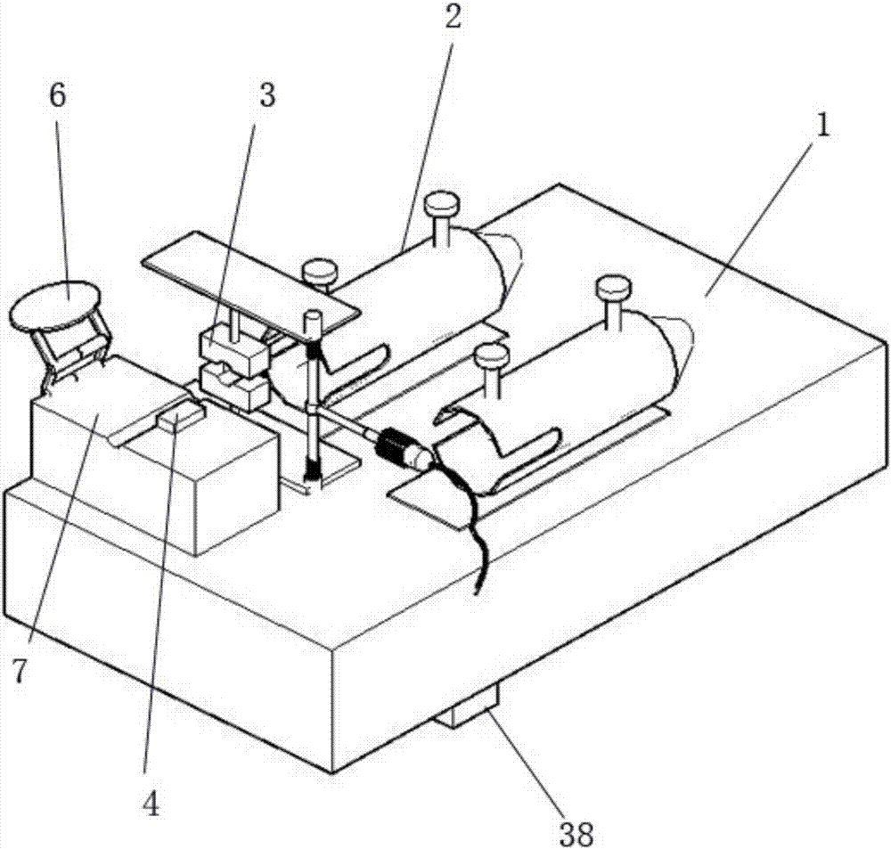
[0075] Please refer to figure 1 , figure 1 It is a structural schematic diagram of a multi-functional mouse tail vein injection platform of the present invention. The mouse tail vein injection platform includes a platform body 1, a mouse cage 2, a pressure regulating device 3, a mouse tail bracket 7, a temperature control device 4, a light guide System device 5, magnifying glass 6; The squirrel cage 2 is fixed on the upper surface of the platform body 1; The front end of the squirrel cage 2 is provided with a pressure regulating device 3; The outside of the pressure regulating device 3 is provided with a mouse tail support Frame 7; one side of the mouse tail bracket 7 is provided with a temperature control device 4; the magnifying glass 6 is arranged on one end edge of the mouse tail bracket 7.
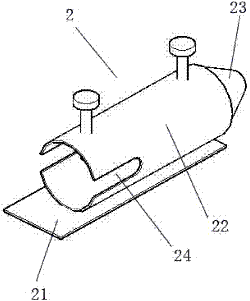
[0076] Please refer to figure 2 , figure 2 It is a schematic diagram of the structure of mouse cage 2. Described squirrel cage 2 comprises connecting plate 21, body 22, plugging...
Embodiment 2
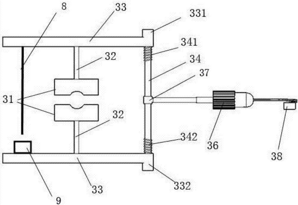
[0089] Please refer to Figure 11 , Figure 11 Schematic diagram of the structure of Embodiment 2 of the present invention. This embodiment is basically the same as Embodiment 1, except that the pressure regulating device 3 includes a lock tongue 31, a connecting rod 32, a pressure block 33, a pressure regulating rod, a reversing joint 37, a rotating shaft 35, Motor 36, knee press switch 38; Described dead bolt 31 is provided with inner concave surface; Described dead bolt 31 has two, and each dead bolt 31 all is to be connected with pressing block 33 by connecting rod 32; One end of the above-mentioned pressure regulating rod is provided with positive thread 341, and the other end of the pressure regulating rod is a smooth structure, and the pressure block 33 corresponding to the positive thread 341 is provided with a positive thread connecting sleeve 331. The briquetting block 33 is provided with a reverse thread connection sleeve 332; one end of the rotating shaft 35 is c...
Embodiment 3
[0092] Please refer to Figure 12 , Figure 12 Schematic diagram of the structure of Embodiment 3 of the present invention. This embodiment is basically the same as Embodiment 1, except that the structure of the pressure regulating device 3 in this embodiment is different. The pressure regulating device 3 in the present embodiment 1 includes a dead bolt 31, a connecting rod 32, a pressurizing block 33, a positive induction coil circuit 39, and a negative induction coil circuit 391; one end of the connecting rod 32 is connected to the dead bolt 31, The other end is connected with the pressurizing block 33; there are two connecting rods 32, one is connected with a positive induction coil circuit 39 on the outer peripheral surface of the connecting rod 32, and the outer peripheral surface of the other connecting rod 32 is provided with a negative induction coil Circuit 391. Compared with Embodiment 1, the voltage regulating device 3 of Embodiment 1 is a purely mechanical struc...
PUM
 Abstract
Description
Claims
Application Information
 - R&D
- Intellectual Property
- Life Sciences
- Materials
- Tech Scout
- Unparalleled Data Quality
- Higher Quality Content
- 60% Fewer Hallucinations
Browse by: Latest US Patents, China's latest patents, Technical Efficacy Thesaurus, Application Domain, Technology Topic, Popular Technical Reports.
© 2025 PatSnap. All rights reserved.Legal|Privacy policy|Modern Slavery Act Transparency Statement|Sitemap|About US| Contact US: help@patsnap.com


