Stamping equipment for medicine bottle cap

A technology for stamping equipment and medicine bottles, applied in the direction of ejection equipment, metal processing equipment, capping, etc., can solve the problems of complex structure, inability to match the feeding mechanism with the stamping mechanism, and difficult to control, so as to achieve simple structure, improve utilization rate, Effect of controlling sheet length

Inactive Publication Date: 2017-11-10
浙江冠利新材料股份有限公司
View PDF0 Cites 3 Cited by
  • Summary
  • Abstract
  • Description
  • Claims
  • Application Information

AI Technical Summary

Problems solved by technology

However, the traditional medicine bottle cap stamping machine has the following shortcomings: 1. The stamping mechanism mainly adopts hydraulic stamping method, which requires hydraulic oil circuit to control the output frequency of the hydraulic cylinder (that is, the stamping frequency), and the structure is too complicated and not easy to control; 2. Both the traditional feeding mechanism and the punching mechanism are driven independently. The feeding frequency and speed of the feeding mechanism and the punching mechanism need to be adjusted and coordinated many times. Even so, the frequency of the feeding mechanism and the punching mechanism cannot be completely consistent. Improve

Method used


Image

  • Stamping equipment for medicine bottle cap
  • Stamping equipment for medicine bottle cap
  • Stamping equipment for medicine bottle cap

Examples


Embodiment Construction

[0017] The preferred embodiments of the present invention will be described in further detail below in conjunction with the accompanying drawings.

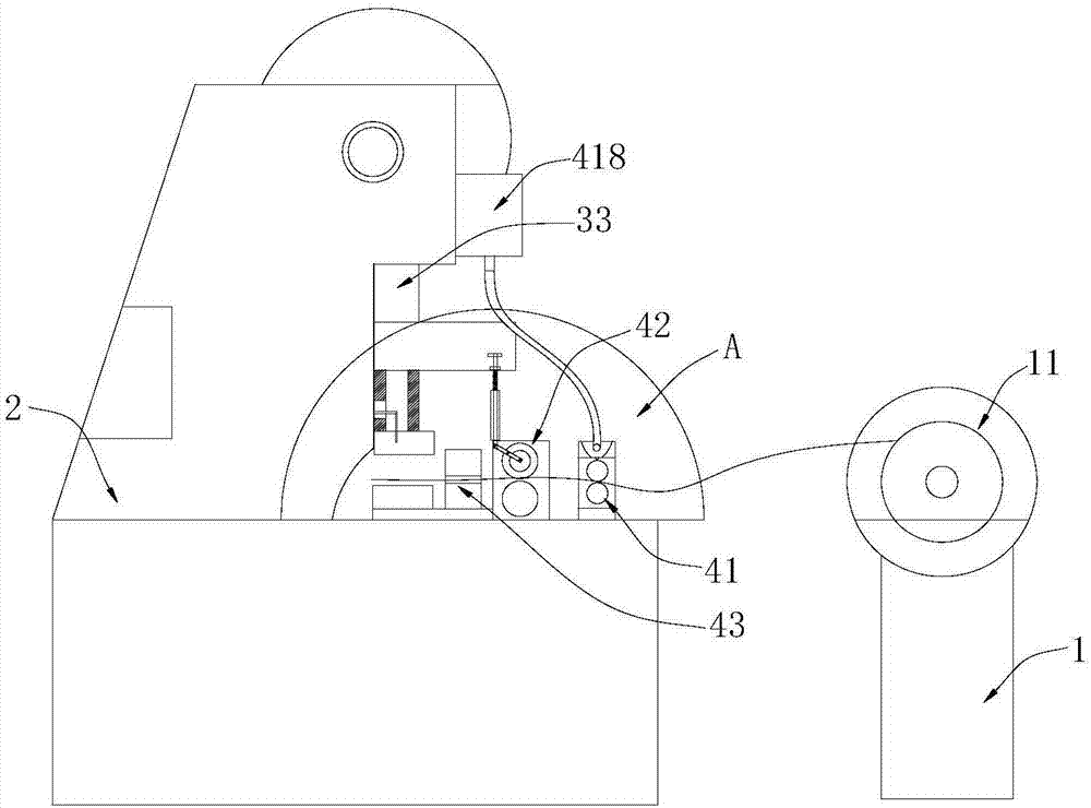
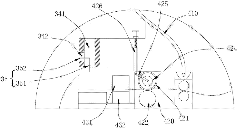
[0018] like Figure 1~4 The medicine bottle cap stamping machine shown includes a tray frame 1, a stamping frame 2, and a stamping mechanism, a feeding mechanism and a blanking mechanism arranged on the stamping frame 2.

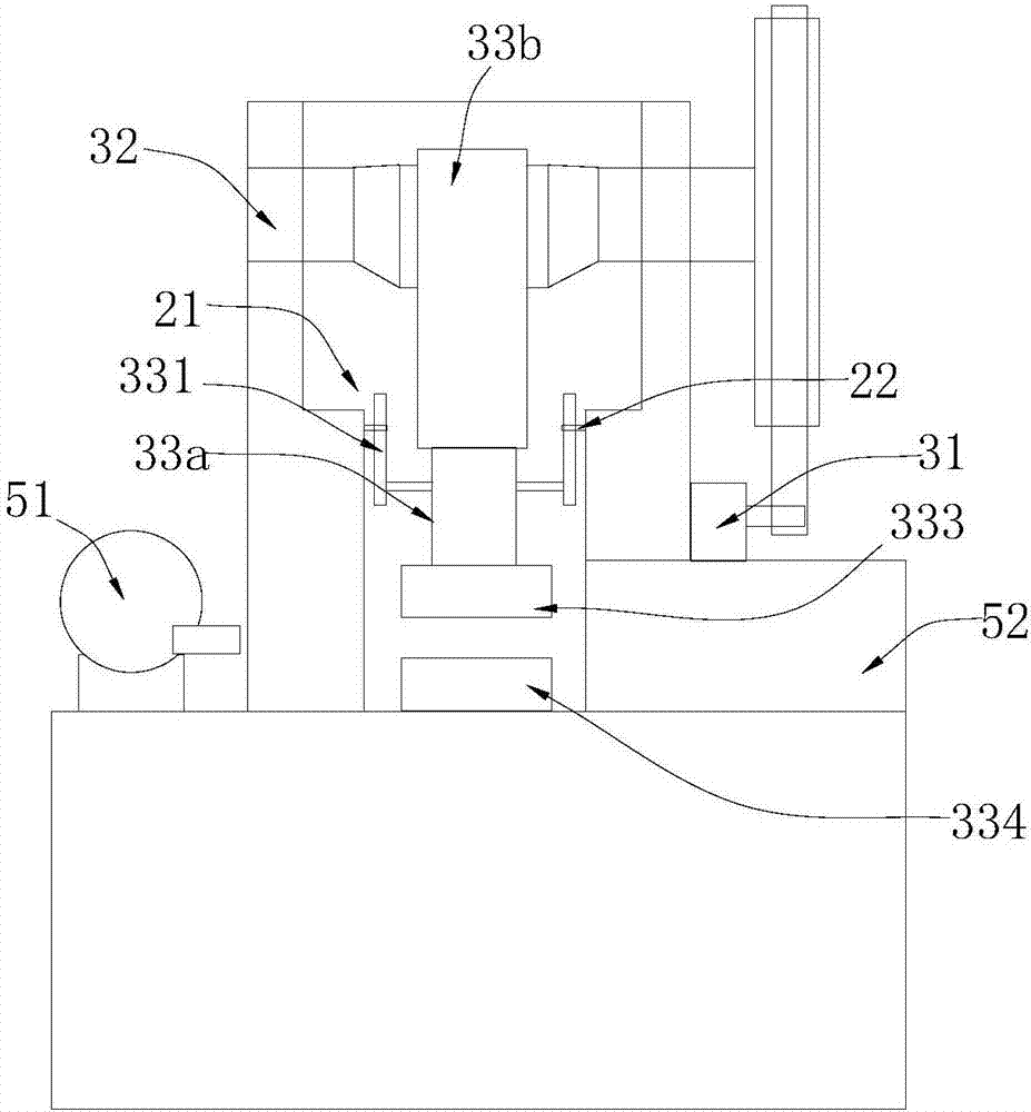
[0019] Described punching mechanism comprises punching motor 31, eccentric shaft 32 and punching shaft 33, the two ends of eccentric shaft 32 are positioned on the punching frame 2 by bearing, punching frame 2 is provided with punching cavity 21, the eccentricity of eccentric shaft 32 The part is located in the upper end of the stamping cavity 21, and the output end of the stamping motor 31 is connected to the eccentric shaft 32 through a transmission assembly. The punching shaft 33 is located in the punching cavity 21 , and the punching shaft 33 includes a punching portion 33 a and a swing portion 33 b hinged ...


PUM


Abstract

The invention relates to the field of bottle cap processing. The medicine bottle cap punching equipment includes a punching mechanism and a feeding mechanism; the punching mechanism includes a punching motor, an eccentric shaft and a punching shaft, and the two ends of the eccentric shaft are positioned on the punching frame through bearings. The output end of the stamping motor is connected to the eccentric shaft through a transmission assembly; the feeding mechanism includes a lubricating roller group, a feeding roller group and a pressing plate group arranged sequentially between the tray frame and the punching station; the feeding roller The set includes a base, and a driving feeding roller and a driven feeding roller positioned on the base, and the other end of the driving feeding roller is linked with the stamping part through a swing arm assembly. The stamping mechanism of the medicine bottle cap stamping equipment has a novel structure, is easy to control and has high stability; in addition, the feeding roller group is linked with the stamping mechanism to ensure the synchronization of the stamping work and the feeding work, to ensure the quality of the stamping, and to facilitate the control of a single The length of the sheet to be fed is conducive to improving the utilization rate of raw aluminum sheets.

Description

technical field [0001] The invention relates to the field of bottle cap processing, in particular to a medicine bottle cap punching equipment. Background technique [0002] Aluminum metal bottle cap is a kind of commonly used medicine bottle cap. The first step in the production process of this kind of metal bottle cap is: stamping and pressing the raw material plate, that is, cutting it from the raw material plate to make the medicine bottle cap The raw material plate is pressed into the basic shape of the medicine bottle cap while stamping. What is used in this production step is a stamping machine used for plate body cutting, and the stamping machine mainly includes a stamping mechanism and a feeding mechanism. However, the traditional medicine bottle cap stamping machine has the following shortcomings: 1. The stamping mechanism mainly adopts hydraulic stamping method, which requires hydraulic oil circuit to control the output frequency of the hydraulic cylinder (that is...

Claims


Application Information

Patent Timeline
Patent Type & Authority Applications(China)
IPC IPC(8): B21D22/02B21D43/02B21D43/08B21D45/02B21D51/48
CPCB21D22/02B21D43/026B21D43/08B21D45/02B21D51/48
Inventor 陈国伟姚卫峰
Owner 浙江冠利新材料股份有限公司
Why Eureka
Try Eureka