Eureka AIR delivers breakthrough ideas for toughest innovation challenges, trusted by R&D personnel around the world.

Up-conversion device of vector signals based on photoelectric oscillator

A technology of photoelectric oscillator and vector signal, which is applied in the direction of optical demodulation, optics, instruments, etc., can solve the problems of high-cost radio frequency signal sources, and achieve the effects of improving signal-to-noise ratio, offsetting noise interference, and low phase noise

Active Publication Date: 2017-11-10
ZHEJIANG UNIV
View PDF7 Cites 8 Cited by
  • Summary
  • Abstract
  • Description
  • Claims
  • Application Information

AI Technical Summary

Problems solved by technology

In "Afull-band RF photonic receiver based on the integrated ultra-high Qbandpass filter" by Hongchen Yu et al. (Optical Fiber Communications Conference and Exhibition 2015, pages 1-3), a cascade of two Mach-Zehnder modulators is proposed The concept of down-conversion is realized. In this scheme, a Mach-Zehnder modulator is used to modulate the local oscillator signal onto the optical carrier, and an optical cross-wavelength division multiplexer is used to separate the positive and negative first-order sidebands of the modulated optical signal. A phase modulator modulates the radio frequency signal to be processed to the positive first-order sideband optical signal, and then uses a photodetector to beat it with the negative first-order sideband to obtain a down-converted electrical signal, ensuring a large noise-free However, it is necessary to modulate the baseband signal to the RF signal and then convert the frequency. At the same time, when a large range of frequency conversion is required, a high-cost RF signal source is still required as a local oscillator.

Method used


Image

  • Up-conversion device of vector signals based on photoelectric oscillator
  • Up-conversion device of vector signals based on photoelectric oscillator
  • Up-conversion device of vector signals based on photoelectric oscillator

Examples


Embodiment Construction

[0049] In order to describe the present invention more specifically, the technical solutions of the present invention will be described in detail below in conjunction with the accompanying drawings and specific embodiments.

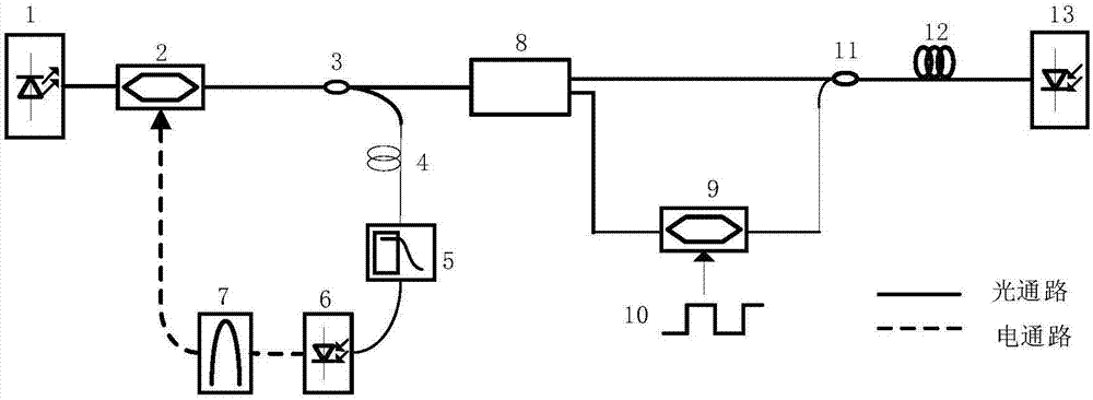
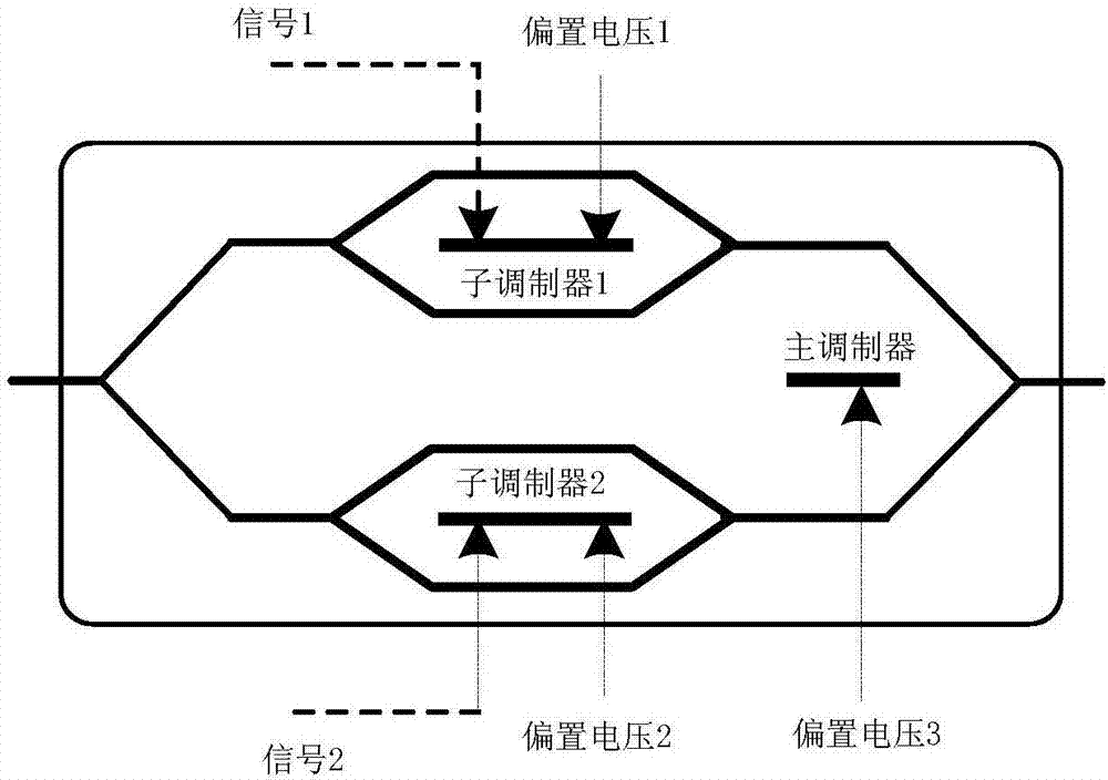
[0050] Such as figure 1 As shown, the vector signal up-conversion device based on an optoelectronic oscillator includes a laser 1, a first electro-optic modulator 2, a first fiber coupler 3, a first optical fiber 4, a first filter 5, a first photodetector 6, a first A second filter 7 , an optical cross-wavelength division multiplexer 8 , a second electro-optic modulator 9 , a baseband signal to be processed 10 , a second fiber coupler 11 , a second optical fiber 12 , and a second photodetector 13 .

[0051] Laser 1 is a distributed feedback filter with high power output to ensure the gain of the system.

[0052] The first electro-optic modulator 2 is a lithium niobate Mach-Zehnder modulator, which is used for intensity modulation of the radio frequency s...


PUM


Abstract

The invention discloses an up-conversion device of vector signals based on a photoelectric oscillator The device comprises a laser device, a first photoelectric modulator, a first optical fiber coupler, a first optical fiber, a first filter, a first photoelectric detector, a second filter, an optical crossover wavelength division multiplexer, a second photoelectric modulator, a second optical fiber coupler, a second optical fiber and a second photoelectric detector. In comparison with a traditional microwave photon up-conversion system, the device has the advantages that baseband signals do not need to be modulated onto microwave signals and frequency-conversion modulation of the baseband signals are directly conducted on optical carrier waves, so operations are more convenient; and positive and negative first-order sideband beat frequencies of the same channel of optical signals can be used to conduct up-conversion of two folds of a local frequency, most noise disturbance is offset, and a signal to noise ratio is increased.

Description

technical field [0001] The invention relates to the field of microwave photon frequency conversion, in particular to a vector signal up-conversion device based on a photoelectric oscillator. Background technique [0002] Microwave technology is currently used in many fields such as wireless communication, electronic countermeasures, radar detection, satellite communication and navigation. In fact, the frequency band resources in the low frequency band are almost exhausted. In order to obtain a larger working bandwidth, researchers have turned their attention to higher frequency bands, especially the millimeter wave band of 30-300GHz. The multi-state conversion of traditional electrical mixers limits the dynamic range of frequency conversion, and at the same time the modulation range and bandwidth are limited, while microwave photonic frequency conversion technology has the advantages of low loss, high bandwidth, anti-electromagnetic interference, simplicity and portability, ...

Claims


Application Information

Patent Timeline
Patent Type & Authority Applications(China)
IPC IPC(8): G02F2/02G02F2/00
CPCG02F2/004G02F2/02
Inventor 张程慧金晓峰余显斌金向东章献民池灏郑史烈
Owner ZHEJIANG UNIV
Why Eureka
Eureka Blog
Learn More