
Real-time correction method of grating interferometer alignment error

A grating interference and alignment error technology, applied to instruments, optical devices, measuring devices, etc., can solve the problems of inconsistent displacement values, installation alignment errors, and the accuracy of measurement results are greatly affected, and improve the measurement accuracy and error. Small, easy-to-measure effects

Inactive Publication Date: 2017-11-14
HEFEI UNIV OF TECH
View PDF2 Cites 17 Cited by
  • Summary
  • Abstract
  • Description
  • Claims
  • Application Information

AI Technical Summary

Problems solved by technology

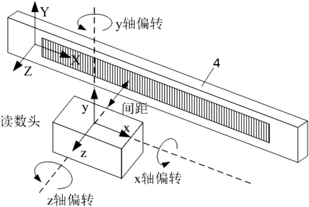
In actual use, due to installation alignment errors and guide rail straightness errors, the x-axis, y-axis and z-axis deflection errors of the optical readhead relative to the grating ruler cause the displacement measurement value calculated by the readhead based on the interference signal to correspond to the grating ruler. Displacement values ​​are inconsistent, which has a great impact on the accuracy of measurement results

Method used


Image

  • Real-time correction method of grating interferometer alignment error
  • Real-time correction method of grating interferometer alignment error
  • Real-time correction method of grating interferometer alignment error

Examples


Embodiment Construction

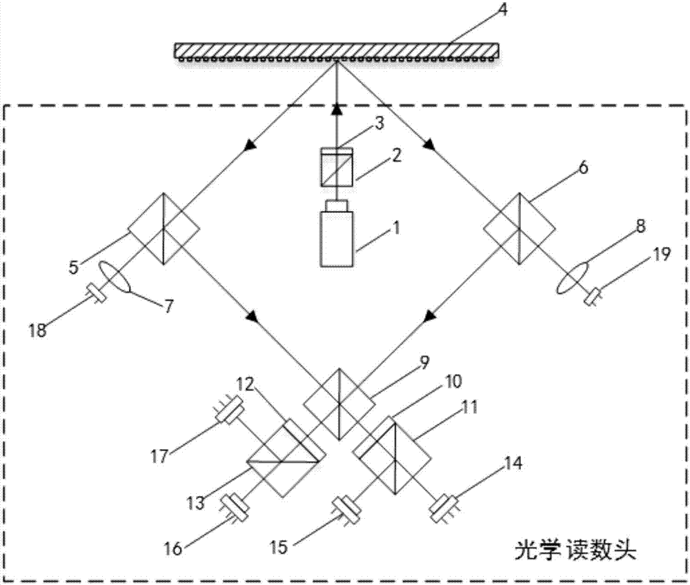
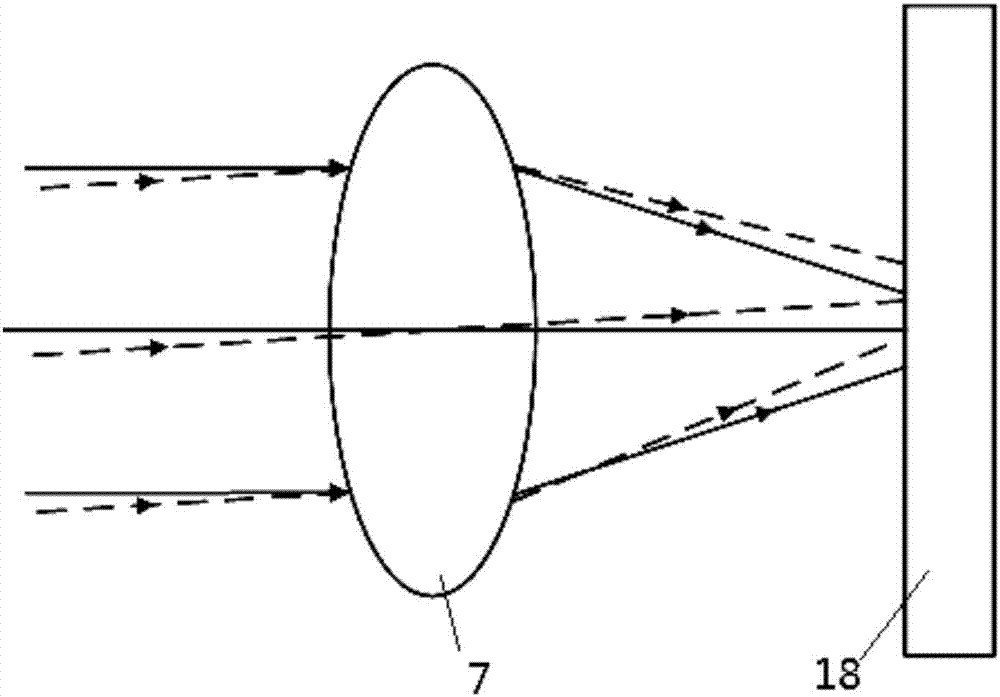
[0017] Such as figure 2 , 3 , 4, and 5, a real-time correction method for grating interferometer alignment error, including a grating interferometer displacement measurement optical path 20, a pose deflection detection optical path 21, a photoelectric detection module 22, an interference signal processing and error compensation module 23, Described grating interferometer displacement measuring optical path 20 comprises laser device 1, polarization beam splitter one 2, quarter wave plate one 3, grating ruler 4, polarization beam splitter two 9, quarter wave plate two 10, polarization Beam splitter three 11, quarter wave plate three 12, polarization beam splitter four 13, electric detector one 14, electric detector two 15, electric detector three 16, electric detector four 17; described pose deflection The detection optical path 21 includes a half-mirror one 5, a half-mirror two 6, a focusing lens 7 and a focusing lens two 8, a four-quadrant detector one 18, and a four-quadran...


PUM


Abstract

The invention discloses a real-time correction method of a grating interferometer alignment error. A grating interferometer displacement measurement optical path, a pose deflection detection optical path, a photoelectric detection module, and an interferometer signal processing and error compensation module are comprised. The grating interferometer displacement measurement optical path is mainly composed of a laser light source, a grating, a non-polarizing beam splitter, a polarizing beam splitter and a quarter-wave plate. The pose deflection detection optical path is mainly composed of a semi-transparent and semi-reflective mirror and a focusing lens. The interferometer signal processing and error compensation module processes grating interferometer signal displacement demodulation and grating measurement error compensation. According to the invention, the symmetrical optical path and a four-quadrant detector are used to measure the deflection about the x, y, and z axes of an optical reading head with respect to the grating ruler's space pose; the real-time correction of the displacement measurement is realized through the error compensation model; finally the measurement accuracy of a grating interferometer is improved; and the method has the advantages of simple measurement and small error.

Description

technical field [0001] The invention relates to the technical field of precision measurement, in particular to a method for real-time correction of an alignment error of a grating interferometer. Background technique [0002] Grating interferometer is an effective method and technology in precision measurement technology. Compared with traditional single-frequency and dual-frequency laser interferometers, the displacement measurement benchmark of the grating interferometer is the grating pitch, and the measurement benchmark of the laser interferometer is the laser wavelength, the grating interferometer can use semiconductor laser diode as the laser light source, and the requirements for the laser light source are lower than those of the laser interferometer, which reduces the cost of the light source. Air turbulence, humidity, temperature) affect the measurement accuracy. [0003] In the grating interferometer measurement system, the alignment error between the optical read...

Claims


Application Information

Patent Timeline
Patent Type & Authority Applications(China)
IPC IPC(8): G01B9/02
CPCG01B9/02072
Inventor 夏豪杰张欣于连栋李维诗陈长春胡梦雯张海铖吴晓婷
Owner HEFEI UNIV OF TECH
Learn More