Master-slave parallel control method for energy storage converters of photovoltaic/battery micro grid system

An energy storage converter and system energy storage technology, which is applied in photovoltaic power generation, electrical components, energy storage, etc., can solve problems such as large reactance, main energy storage converter protection, and complex expansion of the microgrid system, achieving convenience The effect of expansion

Inactive Publication Date: 2017-11-14
北京科诺伟业科技股份有限公司
View PDF1 Cites 23 Cited by
  • Summary
  • Abstract
  • Description
  • Claims
  • Application Information

AI Technical Summary

Problems solved by technology

However, droop control is suitable for high-voltage transmission lines with large reactance and low resistance. At present, the photovoltaic storage microgrid system is generally connected to the low-voltage distribution network, and the transmission line parameters are just the opposite, which makes it difficult for droop control to operate in the actual photovoltaic storage microgrid system.
[0004] The commonly used master-slave parallel control is to send power scheduling instructions from the master energy storage converter to schedule the power of the slave energy storage converters. Ho

Method used


Image

  • Master-slave parallel control method for energy storage converters of photovoltaic/battery micro grid system
  • Master-slave parallel control method for energy storage converters of photovoltaic/battery micro grid system
  • Master-slave parallel control method for energy storage converters of photovoltaic/battery micro grid system

Examples


Embodiment Construction

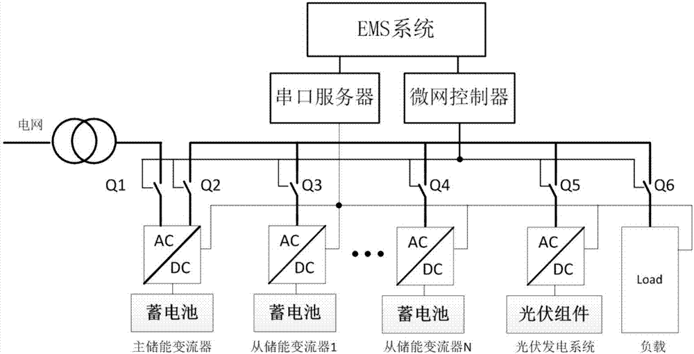
[0019] The present invention will be further described below in conjunction with the accompanying drawings and specific embodiments.

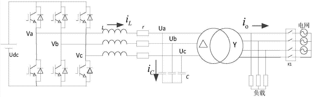
[0020] Such as figure 1 As shown, the optical storage micro-grid system of the present invention includes a main energy storage system, a secondary energy storage system, a photovoltaic power generation system, a load and an energy management system, wherein both the main energy storage system and the secondary energy storage system include batteries and energy storage transformers. converter, and the storage battery is connected to the DC terminal of the energy storage converter. Such as figure 2 As shown, the energy storage of the main energy storage conversion system is a three-port device, which are DC port, grid-connected side port and off-grid side port. The energy storage converter, photovoltaic power generation system and load of the energy storage conversion system are connected to the off-grid side bus of the energy storage convert...


PUM


Abstract

Provided is a master-slave parallel control method for energy storage converters of a photovoltaic/battery micro grid system. When the grid works normally, the maser energy storage converter and the slave energy storage converters of the photovoltaic/battery micro grid system both work in a grid-connected mode, and a three-stage charging strategy including constant-current charging, constant-voltage charging and floating charging is implemented according to the battery state of the energy storage systems. When the grid fails, the master energy storage system is switched to an off-grid mode to establish a voltage and a frequency for the bus of the photovoltaic/battery micro grid system, and the slave energy storage systems continue to work in a grid-connected mode. An energy management system adjusts the output power of the energy storage converters in the slave energy storage systems in real time according to the load power, the state of the master energy storage system and the power of a photovoltaic power generation system, in order to maintain the power balance in the micro grid system. In order to meet the power allocation requirement of each energy storage system in the photovoltaic/battery micro grid system, the energy management system issues power dispatching instructions to the slave energy storage converters according to the battery state, the generation power of the photovoltaic system and the load power.

Description

technical field [0001] The invention relates to a control method for master-slave parallel operation of multiple energy storage converters in an optical storage microgrid system. Background technique [0002] With the rapid development of distributed new energy, microgrid systems that can be flexibly switched between grid-connected and off-grid are becoming more and more widely used. The microgrid system is a small power generation and distribution system consisting of distributed power sources, power loads, power distribution facilities, monitoring and protection devices, and energy storage devices when necessary. When the power grid is normal, the optical storage microgrid system operates in the grid-connected mode, and the energy storage converters in the optical storage microgrid system achieve the set operation goals according to the preset operation management strategy. When the power grid fails, the photovoltaic storage microgrid system switches to the off-grid mode,...

Claims


Application Information

Patent Timeline
IPC IPC(8): H02J3/38H02J3/46H02J3/32
CPCH02J3/32H02J3/383H02J3/46Y02E10/56Y02E70/30
Inventor 樊晓磊许洪华
Owner 北京科诺伟业科技股份有限公司
Why Eureka
Try Eureka