Supercharge Your Innovation With Domain-Expert AI Agents!

Laminated spiral type dewatering machine capable of inputting mud from tail end

A dehydrator and screw technology, which is applied in water/sludge/sewage treatment, dehydration/drying/concentrated sludge treatment, sludge treatment, etc., can solve the problems of overall assembly impact, high processing difficulty and low precision, etc. Achieve the effect of low cost, low processing difficulty and high filtration efficiency

Pending Publication Date: 2017-11-17
AMCON FUJIAN ENVIRONMENT PROTECTION EQUIP CO LTD
View PDF12 Cites 0 Cited by
  • Summary
  • Abstract
  • Description
  • Claims
  • Application Information

AI Technical Summary

Problems solved by technology

But there is following shortcoming in this mud inlet box structure: (1), because mud inlet 5 is on the top, so will make a sleeve 4 that can accommodate down mud inlet pipe, this part is only used for mud inlet, cannot implement filtering
Therefore, with the screw shaft of the same length, the filter effect of the dewatering machine with mud entering above is slightly worse; (2), when the support plate 3 at the tail end of the solid-liquid separation part 1 is welded with the sleeve 4, due to the realization of the sleeve 4, The concentricity of the solid-liquid separation part 1 and the shaft sleeve 6 is difficult to process, easily deformed, and the precision is not high, which will affect the subsequent overall assembly
(3), the processing cost is expensive

Method used


Image

  • Laminated spiral type dewatering machine capable of inputting mud from tail end
  • Laminated spiral type dewatering machine capable of inputting mud from tail end
  • Laminated spiral type dewatering machine capable of inputting mud from tail end

Examples


no. 1 example

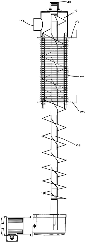
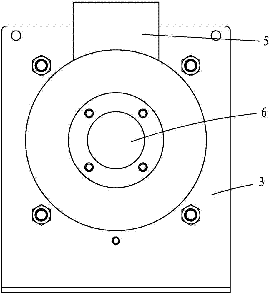
[0024] like Figure 3 to Figure 6 As shown, a stacked spiral dehydrator with mud feeding at the tail end, including a solid-liquid separation part 1 with fixed rings and movable rings staggered, and a screw shaft 2 passing through the solid-liquid separation part 1, located in the dehydration The mud outlet (not shown) at the head end of the machine main body, the mud inlet 5 at the tail end of the dehydrator main body; the solid-liquid separation part 1 is supported by a plurality of support plates 3; the tail end of the screw shaft 2 is supported by a The shaft sleeve 6 is supported; the shaft sleeve 6 is fixedly arranged on the support plate 3 at the tail end of the main body of the dehydrator; the mud inlet 5 is located on the support plate 3 at the main end of the dehydrator and above the shaft sleeve 6; The mud inlet 5 is connected to the solid-liquid separation part 1 through a mud inlet structure 7 .

[0025] The mud inlet structure 7 includes a complex fixed ring 71 ...

no. 2 example

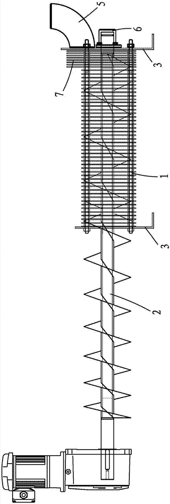
[0027] like Figure 7 to Figure 10 As shown, the difference from the first embodiment is that the tail end of the double screw shaft is used to enter the stacked spiral dehydrator.

[0028] The mud inlet structure part in the present invention can also be filtered, and the length of the mud inlet structure is shorter than the length of the prior art sleeve, therefore, the dehydrator with the same length screw shaft has high filtration efficiency in the present invention; no additional welding of the sleeve is required, The processing difficulty is small; the cost is low.


PUM


Abstract

The invention provides a laminated spiral type dewatering machine capable of inputting mud from a tail end. The laminated spiral type dewatering machine comprises a solid-liquid separation part which is formed by arraying a fixed ring and a movable ring in a staggered manner, at least one spiral shaft which penetrates through the solid-liquid separation part, a mud outlet which is located at a front end of a dewatering machine main body and a mud inlet which is located at the tail end of the dewatering machine main body, wherein the solid-liquid separation part is supported through a plurality of supporting plates; the tail end of the spiral shaft is supported by a shaft sleeve; the shaft sleeve is fixedly arranged on the supporting plate which is fixedly arranged at the tail end of the dewatering machine main body; the mud inlet is located on the supporting plate which is located at the tail end of the dewatering machine main body and is located above the shaft sleeve; the mud inlet is connected with the solid-liquid separation part through a mud feeding structure. According to the laminated spiral type dewatering machine provided by the invention, the mud feeding structure part can also be used for filtering and the length of the mud feeding structure is less than that of a sleeve in the prior art, so that the dewatering machine with the spiral shaft with the same length has higher filtering efficiency; a sleeve does not need to be additionally welded so that the machining difficulty is small and the cost is low.

Description

【Technical field】 [0001] The invention belongs to the technical field of sludge treatment equipment, and in particular relates to a stacked spiral dehydrator with sludge feeding from the tail end. 【Background technique】 [0002] Chinese invention patent 200780018706.9 discloses a stacked screw type solid-liquid separation device, which is equipped with a plurality of adjacent fixed rings and a solid-liquid separation part of a plurality of movable rings arranged between the adjacent fixed rings, and a solid-liquid separation part that passes through the At least one screw extending from the solid-liquid separation part, the movable ring is used to push the above-mentioned movable ring through the rotating screw, and at the same time, the object to be treated that enters the solid-liquid separation part is directed towards the side of the solid-liquid separation part through the rotating screw The filtrate separated from the object to be processed passes through the solid-liq...

Claims


Application Information

Patent Timeline
Patent Type & Authority Applications(China)
IPC IPC(8): C02F11/12
CPCC02F11/121
Inventor 郑朝志
Owner AMCON FUJIAN ENVIRONMENT PROTECTION EQUIP CO LTD
Features
  • R&D
  • Intellectual Property
  • Life Sciences
  • Materials
  • Tech Scout
  • Unparalleled Data Quality
  • Higher Quality Content
  • 60% Fewer Hallucinations
Learn More