Spiral casing pile pulling equipment and spiral casing pile pulling system

A technology of spiral casing and equipment, applied in the field of construction machinery, can solve the problems of low equipment requirements, unsatisfactory pile pulling effect, low pile pulling success rate, etc., and achieves rapid isolation action, good pile pulling effect, and pile pulling efficiency. high effect

Pending Publication Date: 2017-11-17
中铁十一局集团桥梁有限公司 +1
View PDF4 Cites 2 Cited by
  • Summary
  • Abstract
  • Description
  • Claims
  • Application Information

AI Technical Summary

Problems solved by technology

[0003] The inventor found that among the three existing schemes, the first scheme is more advanced in technology and has a high success rate of pile pulling, but the construction equipment is generally imported from abroad, the equipment is expensive, and the construction cost is relatively high; the second scheme The principle of pile pulling is relatively simple, and the construction speed is fast. At present, there are professional foundation companies in China that have applied for patented technology and provided pile pulling and obstacle removal construction services, but the construction cost is relatively high; the third option requires less equipment and less investment. The construction cost is much lower than the previous two schemes, but the possibility of pulling out is higher, and the success rate of pile pulling is lower
The pile pulling effect of the existing pile pulling equipment is not particularly ideal

Method used


Image

  • Spiral casing pile pulling equipment and spiral casing pile pulling system
  • Spiral casing pile pulling equipment and spiral casing pile pulling system
  • Spiral casing pile pulling equipment and spiral casing pile pulling system

Examples


no. 1 example

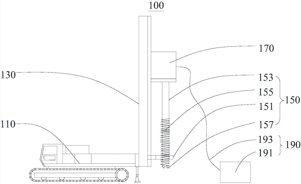
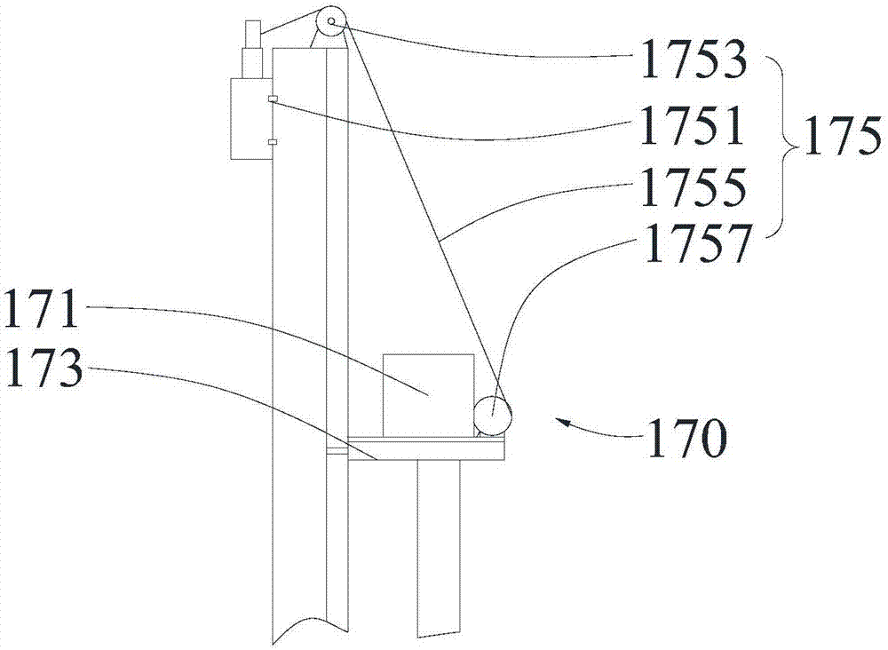
[0033] see figure 1, the present embodiment provides a spiral casing pile pulling device 100 for pulling out pipe piles, the spiral casing pile pulling device 100 includes a pile digger 110, a boom 130, a hole forming device 150, a power device 170 and a mud Circulation device 190, arm frame 130 is connected to an end of pile excavator 110, has slide rail on the arm frame 130, and power unit 170 is slidably connected to slide rail, and one end of mud circulation device 190 stretches into power unit 170 and with hole forming device 150 Connection for injecting mud into the hole forming device 150.

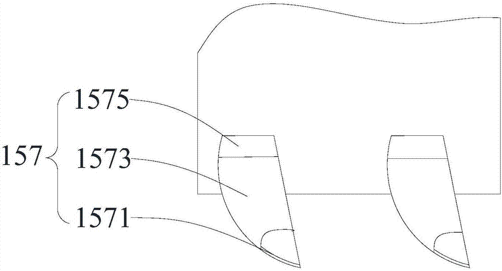
[0034] The hole-forming device 150 includes a positioning sleeve 151, a casing 153, a spiral guide blade 155 and a plurality of cutting cutter heads 157. The positioning sleeve 151 is fixedly connected to one end of the boom 130 close to the pile digger 110, and one end of the casing 153 is detachable. The ground is connected to the power unit 170 and communicates with one end of t...

no. 2 example

[0048] A spiral casing pile pulling system (not shown in the figure) provided in this embodiment is used for pulling out pipe piles, including mud sedimentation circulation equipment (not shown in the figure) and a spiral casing pile pulling device 100, wherein the spiral casing pulling The basic structure, principle and technical effect of the pile equipment 100 are the same as those of the first embodiment. For a brief description, for parts not mentioned in this embodiment, reference may be made to the corresponding content in the first embodiment.

[0049] The spiral casing pile pulling equipment 100 includes a pile digging machine 110, a hole forming device 150, a power unit 170, and a mud circulation device 190. The pile digging machine 110 includes a boom 130 and a hydraulic walking base 111. The boom 130 is connected to the hydraulic walking One end of the base 111 has a slide rail on the boom 130, and the power unit 170 is slidably connected to the slide rail. One end ...


PUM


Abstract

The invention provides spiral casing pile pulling equipment and a spiral casing pile pulling system, and relates to the field of construction machines. The spiral casing pile pulling system comprises slurry sediment circulating equipment and the spiral casing pile pulling equipment. The spiral casing pile pulling equipment comprises a pile excavation machine, an arm support, a pore forming device, a power device and a mud circulating device; the pore forming device comprises a locating sleeve, a casing and a spiral diversion blade; the locating sleeve is fixedly connected with one end, close to a hydraulic travelling base, of the arm support; one end of the casing is detachably connected with the power device, and communicates with one end, stretching into the power device, of the mud circulating device; the other end of the casing penetrates through the locating sleeve; and the spiral diversion blade is fixed at the peripheral surface of the casing spirally. Compared with the prior art, the spiral casing pile pulling equipment is simple in structure, convenient to use and high in pile pulling efficiency, has the excellent pile pulling effect and can rapidly complete isolation movement.

Description

technical field [0001] The invention relates to the field of construction machinery, in particular to a spiral casing pile pulling device and a spiral casing pile pulling system. Background technique [0002] In the field of construction, it is often necessary to pull out the pipe piles that have been driven into the ground. According to the current similar construction conditions at home and abroad, pile pulling is mainly used for the removal of old piles in large and medium-sized buildings in urban construction and subway tunnels. The most important thing in pile pulling is to eliminate or reduce the frictional resistance of the pile side. The existing pile pulling methods are usually through (1) cutting the soil around the pile to pull the pile, (2) vibrating double casing method and (3) full set Pipe vibration assisted pile extraction method is used to pull out pipe piles. [0003] The inventor found that among the three existing schemes, the first scheme is more advanc...

Claims


Application Information

Patent Timeline
IPC IPC(8): E02D9/02E21B10/43E21B17/22
CPCE21B10/43E21B17/22E02D9/02
Inventor 杨忠窦彦杰刘继仁夏斌李建红杨期正曹志超胡伟君
Owner 中铁十一局集团桥梁有限公司
Why Eureka
Try Eureka