Control method for phase modifier oil system

A technology of camera adjustment and oil system, applied in the field of camera adjustment, can solve the problems of time-consuming, laborious, waste of lubricating oil, and increased cost.

Active Publication Date: 2017-11-17
JIANGSU JIANGHAI LUBRICANTS HYDRAULIC EQUIP
View PDF5 Cites 5 Cited by
  • Summary
  • Abstract
  • Description
  • Claims
  • Application Information

AI Technical Summary

Problems solved by technology

[0003] The condenser oil system is a particularly important part of the condenser. The existing condenser oil system and system control have the following shortcomings: 1. The structure of the existing lubricating oil supply system and jacking oil system is relatively simple, and the lubricating oil pump or Usually only one jacking oil pump is installed. During use, once there is a problem with the lubricating oil pump or the jacking oil pump, the entire equipment needs to be stopped for maintenance before it can continue to work. Moreover, the temperature and pressure control of the entire lubricating oil supply system Poor, unable to issue correct instructions, comprehensive inspection and maintenance are required during maintenance, the pressure control of the entire jacking oil system is poor, and the pressure balance of the condenser cannot be guaranteed; 2. There is no special automatic control oil fume recovery system to discharge oil fume, and the discharge of the condenser The oily fumes that come out directly pollute the external environment, and are not conducive to the recycling and reuse of lubricating oil. During the use of the oil conditioner oil system, the lubricating oil gradually decreases, and it is necessary to continuously add lubricating oil, which is time-consuming and laborious, and at the same time increases the cost; 3. Inside the oil tank The lubricating oil is continuously supplied to the condenser. If there is too much lubricating oil, it is easy to overflow and pollute the external environment. At the same time, part of the lubricating oil is wasted, which requires manual cleaning, which is extremely inconvenient.

Method used


Image

  • Control method for phase modifier oil system
  • Control method for phase modifier oil system
  • Control method for phase modifier oil system

Examples


Embodiment Construction

[0033] In order to deepen the understanding of the present invention, the present invention will be further described below in conjunction with the embodiments and accompanying drawings. The embodiments are only used to explain the present invention and do not constitute a limitation to the protection scope of the present invention.

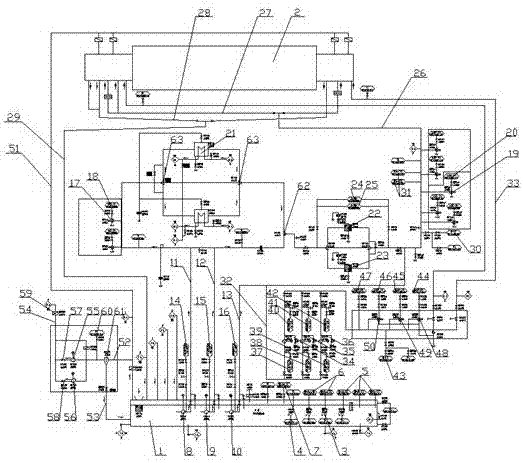
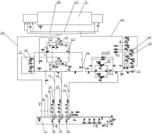
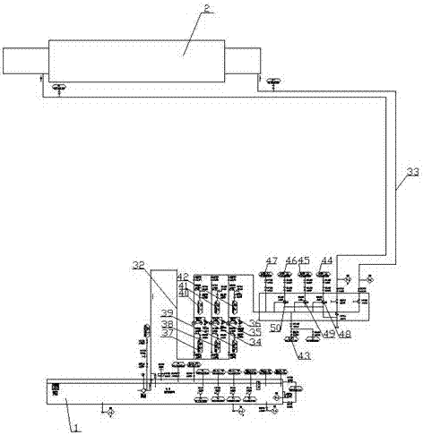
[0034] In this embodiment, a conditioner oil system, such as figure 1 As shown, it includes oil tank 1, condenser 2, lubricating oil supply system, jacking oil system, oil fume recovery system, lubricating oil supply system and jacking oil system are placed between oil tank 1 and condenser 2, oil fume recovery system The inlet end of the oil fume recovery system is connected to the outlet end of the condenser 2, and the outlet end of the oil fume recovery system is divided into two paths, one is connected to the fuel tank 1, and the other is discharged into the air.

[0035]The oil tank is equipped with a heater group, a heater limit temperature ...


PUM


Abstract

The invention discloses a control method for a phase modifier oil system. The control method for the phase modifier oil system comprises the following steps that (1) when starting is conducted, a self-checking signal is sent out by a controller of the phase modifier oil system, a lubricating oil supply system and a jacking oil system conduct self-checking; (2) the controller of the phase modifier oil system controls the temperature and the liquid level of lubricating oil in an oil tank automatically; (3) the controller connected with the oil tank sends out a lubricating oil supply instruction, and the lubricating oil passes a cooler and a filter sequentially and enters a phase modifier; (4) the controller sends out a jacking oil system jacking instruction; (5) the redundant lubricating oil in the phase modifier is controlled by the controller which sends out an oil return signal and enters the oil tank through an oil return pipeline; and (6) the controller sends out a discharge signal aiming at oil smoke of the phase modifier oil system. The control method for the phase modifier oil system has the advantages that full automated control of the phase modifier oil system over supply, jacking, return and oil contamination discharging of the lubricating oil is achieved, and normal operation of the system is ensured under the condition that main parts of the system fail.

Description

Technical field: [0001] The invention relates to the field of condensers, in particular to a condenser oil system. Background technique: [0002] With the continuous development of the power system, in order to reduce various losses in the reciprocating transmission of transmission lines, effectively improve the system voltage level, improve stability, improve the utilization rate of power generation equipment, reduce power loss in the power system, and improve power factor, Therefore, it is necessary to install a certain capacity of reactive power equipment in or around the load center, that is, a condenser, to compensate for the lack of reactive power and improve the economic operation of the power system. The condenser is composed of a stator, a rotor and an excitation system. The absorbing system A small amount of active power is used to supply its own energy loss, to send reactive power to the system or to absorb reactive power. [0003] The condenser oil system is a p...

Claims


Application Information

Patent Timeline
Patent Type & Authority Applications(China)
IPC IPC(8): F16N7/40F16N39/04F16N39/02F16N39/06F16N29/02F16N29/04F16N31/00
CPCF16N7/385F16N7/40F16N29/02F16N29/04F16N31/00F16N39/002F16N39/02F16N39/04F16N39/06F16N2039/007F16N2230/18F16N2250/04F16N2250/08F16N2260/04F16N2260/06F16N2270/72
Inventor 李大选郭艳妮张红日王秋宝
Owner JIANGSU JIANGHAI LUBRICANTS HYDRAULIC EQUIP
Why Eureka
Try Eureka