
Phase change heat storage header type condensation radiant panel

A phase-change heat storage and radiant panel technology, which is applied in the heating method, heat storage equipment, heat exchanger type, etc., can solve the heat loss, affect the operation efficiency of the air source heat pump system in winter and indoor thermal comfort, and cannot take into account the summer. Air conditioning and refrigeration problems, to achieve the effect of reducing resistance, slowing down the phenomenon of hot lines, reducing energy consumption and energy loss in transportation

Pending Publication Date: 2017-11-17
TIANJIN UNIV
View PDF6 Cites 7 Cited by
  • Summary
  • Abstract
  • Description
  • Claims
  • Application Information

AI Technical Summary

Problems solved by technology

However, the system needs to perform secondary heat exchange with water during operation, resulting in a certain amount of heat loss, and the system is only used for heating in winter, and cannot take into account the problem of air conditioning and cooling in summer
At the same time, the frost on the surface of the evaporator of the outdoor unit of the air source heat pump will affect the operating efficiency of the air source heat pump system in winter and the indoor thermal comfort, and it has also become a problem in the winter operation of the above two heating systems

Method used


Image

  • Phase change heat storage header type condensation radiant panel
  • Phase change heat storage header type condensation radiant panel
  • Phase change heat storage header type condensation radiant panel

Examples


Embodiment Construction

[0020] The technical solution of the present invention will be further described in detail below in conjunction with the accompanying drawings and specific embodiments, and the described specific embodiments are only for explaining the present invention, and are not intended to limit the present invention.

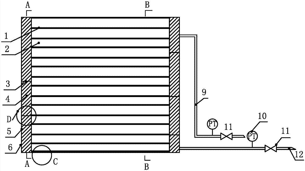
[0021] As shown in Figure 1(a), a phase-change heat storage collector-type condensing radiant panel proposed by the present invention includes a heat supply pipeline and a header-type radiant panel, and the heat supply pipeline includes a heat supply dry pipe 9 and heat recovery main pipe 12, the heat supply main pipe 9 and the heat recovery main pipe 12 are equipped with temperature and pressure sensors 10 and control valves 11; Between the heat recovery dry pipes 12 .

[0022] As shown in Figure 1(a), the header-type radiant panel includes a galvanized steel plate shell 5, and the two ends of the galvanized steel plate shell 5 are separated by galvanized steel plates to ...


PUM


Abstract

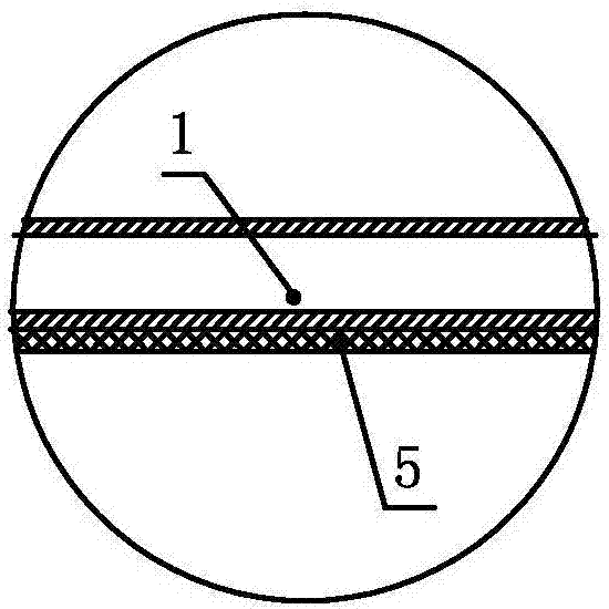
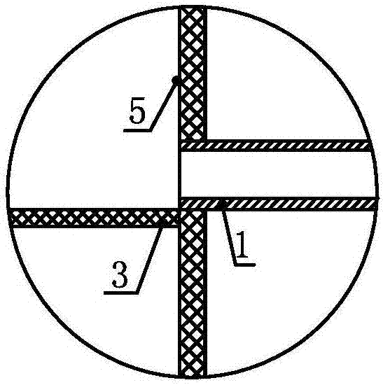
The invention discloses a phase change heat storage header type condensation radiant panel which comprises a heat supply pipeline and a header type radiant panel body. The header type radiant panel body comprises a galvanized steel plate shell. After each of the two ends of the galvanized steel plate shell is separated by a galvanized steel plate, a gas-liquid cavity is formed. Multiple heating pipes are connected between the gas-liquid cavities at the two ends in parallel, and each heating pipe is filled with refrigerating fluid. The space between the outer wall of each heating pipe and the galvanized steel plate shell is filled with a phase change heat storage layer. Multiple partition plates are arranged in each gas-liquid cavity. The partition plates in the gas-liquid cavities in the two sides are staggered in height, and therefore the interiors of the gas-liquid cavities in the two sides are divided into multiple gas-liquid channels through the partition plates. The multiple adjacent heating pipes are connected in series through the gas-liquid channels according to the arrangement of the partition plates to form a heating pipe bundle, wherein the gas-liquid channels are in end-to-end connection with the heating pipes and located on the two sides. The outer surface of the galvanized steel plate shell is coated with a radiant coating layer. According to the phase change heat storage header type condensation radiant panel, modular production and field splicing mounting can be achieved; the construction difficulty can be reduced; modification on building basic facilities and indoor layout is small; the work amount is reduced; and the cost is reduced.

Description

technical field [0001] The invention relates to a heating device hung on a wall, in particular to a new type of phase change heat storage collector type condensing radiant panel device for indoor heating in winter and summer of a double-end air source heat pump system. Background technique [0002] With the increasingly serious problem of energy shortage and environmental pollution, the state proposes to use electric heating facilities as a supplementary heating method to replace the original fossil energy scattered combustion facilities for the non-centralized heating areas in the north, so as to reduce the environmental pollution caused by scattered coal combustion . Among the existing electric heating facilities, the electric-driven air source heat pump obtains heat from the air and converts low-grade heat energy into high-grade heat energy for heating. It is the most energy-saving and easiest heating facility. [0003] Traditional air source heat pump cooling and heatin...

Claims


Application Information

Patent Timeline
Patent Type & Authority Applications(China)
IPC IPC(8): F24D19/00F24D15/02F24D15/04F28D20/02
CPCF24D15/02F24D15/04F24D19/00F28D20/02F24D2200/12Y02B30/12Y02E60/14
Inventor 张欢邵索拉由世俊叶天震郑雪晶郑万冬
Owner TIANJIN UNIV
Learn More