
A Multiport DC-DC Transformer System Topology with Stepless Regulation of DC Voltage

A DC transformation and DC voltage technology, which is applied in the direction of converting AC power input to DC power output, electrical components, power transmission AC network, etc. The effect of fault isolation, good DC fault isolation performance

Active Publication Date: 2020-12-11
NORTH CHINA ELECTRIC POWER UNIV (BAODING)
View PDF5 Cites 0 Cited by
  • Summary
  • Abstract
  • Description
  • Claims
  • Application Information

AI Technical Summary

Problems solved by technology

At present, there have been literatures on DC / DC converter research, such as the use of chopper circuits in the low-voltage field, but if it is applied to the field of DC transmission, multiple IGBTs need to be directly connected in series, which is technically difficult; another example is the use of three-phase Active bridge (Dual-active-bridge, DAB) technology constructs DC-DC converters. The advantage of this technology is that it can reduce the size when operating at high frequency, and the loss is relatively small. However, in the field of DC power transmission, especially onshore DC power transmission Pay attention to the operation loss of the whole system. Whether this technology is suitable for onshore DC power transmission needs to be verified; another example is the use of multi-port DC-DC conversion technology based on inductance-capacitance-inductance circuits. One of the main starting points of this technology is to save transformers and Reduce the platform area, so that it can be easily applied to offshore DC transmission. Similarly, whether this technology is suitable for land DC transmission is also open to question

Method used


Image

  • A Multiport DC-DC Transformer System Topology with Stepless Regulation of DC Voltage
  • A Multiport DC-DC Transformer System Topology with Stepless Regulation of DC Voltage
  • A Multiport DC-DC Transformer System Topology with Stepless Regulation of DC Voltage

Examples


Embodiment Construction

[0045] The specific embodiments of the present invention will be further described in detail below in conjunction with the accompanying drawings.

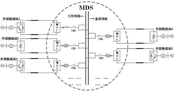
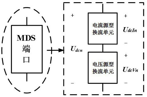
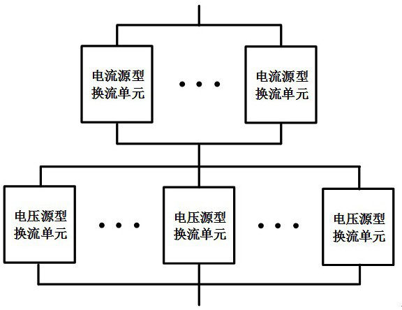
[0046] A multiport DC-DC transformer system (Multiport DC / DCSystem, MDS) topology with stepless DC voltage regulation, the MDS has multiple ports for interconnection with an external DC system; the topology of each port of the MDS A hybrid series converter is adopted; the AC side of the hybrid series converter is connected to the common AC bus inside the MDS through an AC circuit breaker, and an AC transformer is used inside the MDS to match hybrid series converters of different voltage levels. Converter, so that MDS has the function of connecting DC lines of different voltage levels. The hybrid series converter is composed of a current source type converter unit and a voltage source type converter unit in series, and the current source type converter unit includes an LCC structure based on a diode or a thyristor; the voltage sourc...


PUM


Abstract

The present invention provides a multiport DC-DC transformer system (Multiport DC / DC System, MDS) topology with stepless regulation of DC voltage. The MDS has a plurality of ports for interconnecting external DC systems; the ports adopt a hybrid series type For the converter, the AC side is connected to the common AC bus in the MDS through the AC circuit breaker; the MDS uses a transformer to match the DC lines of different voltage levels. The hybrid series converter uses current source and voltage source commutation units in series: the current source commutation unit contains LCCs based on diodes or thyristors; the voltage source commutation unit has a modular multilevel structure, and each bridge The arms are cascaded by sub-modules without negative level output (such as IGBT components, HBSM) and with negative level output capability (such as FBSM). The MDS has the ability to steplessly adjust DC voltage (even reverse polarity); has both DC fault ride-through and fast recovery capabilities; and helps to quickly realize power flow reversal. Therefore, the proposed MDS topology is helpful to promote the application of multi-port DC-DC converters in DC grids.

Description

technical field [0001] The invention relates to a device in the technical field of power transmission and distribution, in particular to a multi-port DC-DC transformer system topology with stepless regulation of DC voltage. Background technique [0002] With more and more new energy sources such as wind power and solar power connected to the grid and the development of DC transmission technology, a multi-terminal DC transmission technology has been formed on the basis of point-to-point HVDC technology, and has further developed into a DC power grid. A technology that directly constitutes a DC grid is to interconnect multiple DC lines on the DC side. However, due to the immature technology of DC circuit breakers and DC grid protection, this DC grid technology faces many challenges and technical difficulties, mainly as follows: 1 ) DC lines with different voltage levels cannot be interconnected; 2) It is weak to deal with DC faults. A DC fault at any point in the DC grid will ...

Claims


Application Information

Patent Timeline
Patent Type & Authority Patents(China)
IPC IPC(8): H02J3/36H02M7/483
CPCH02J3/36H02M7/483H02M7/4835Y02E60/60
Inventor 郭春义王烨赵成勇王一凡许建中
Owner NORTH CHINA ELECTRIC POWER UNIV (BAODING)
Learn More