
Bi-directional draught fan power device

A power device and two-way fan technology, applied in the field of pneumatic transmission, can solve problems such as complex structure, complex gas path, and large space occupation

Pending Publication Date: 2017-11-21
厦门赛摩积硕科技有限公司
View PDF4 Cites 1 Cited by
  • Summary
  • Abstract
  • Description
  • Claims
  • Application Information

AI Technical Summary

Problems solved by technology

[0005] The purpose of the present invention is to provide a two-way fan power device to solve the problems of complex structure or complex gas path and large space occupation of the existing fan power device for pneumatic transmission

Method used


Image

  • Bi-directional draught fan power device
  • Bi-directional draught fan power device
  • Bi-directional draught fan power device

Examples


Embodiment 1

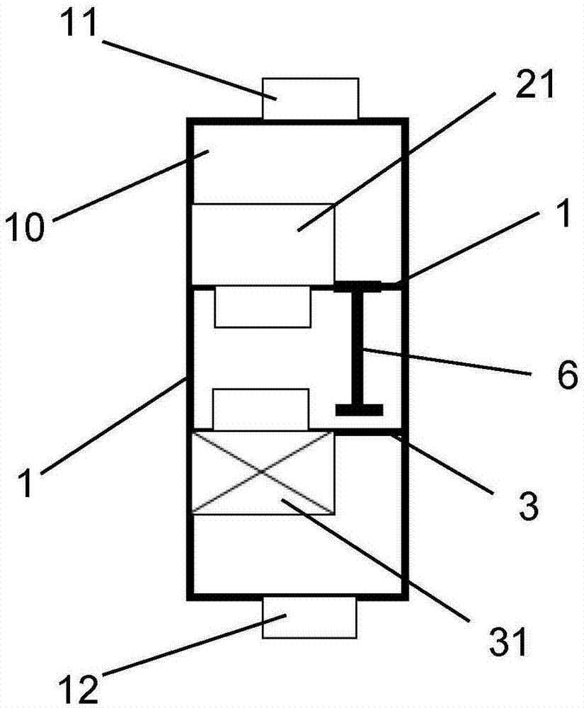
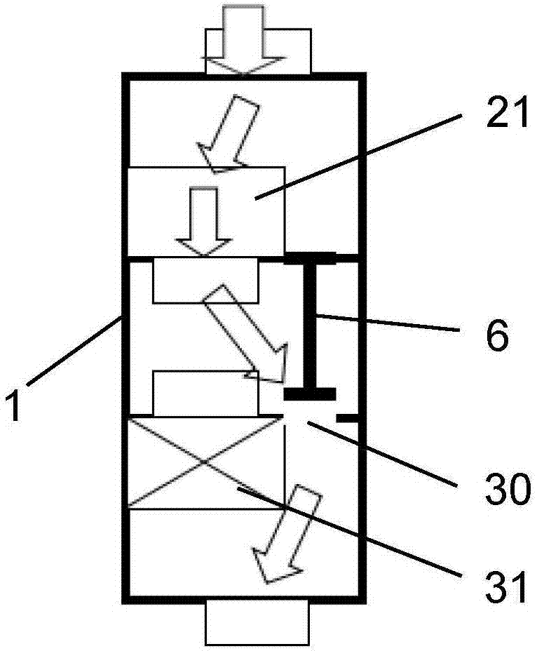
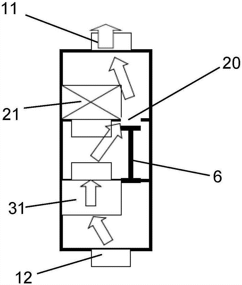
[0027] combine Figure 1 to Figure 3 As shown, this embodiment discloses a two-way fan power device, which includes a box body 1, the front and rear ends of the box body 1 are respectively provided with user ports 11 and external ports 12, and the box body is provided with an air duct 10, Both ends of the air duct 10 are connected to the user port 11 and the external port 12 respectively, and the rest of the air duct 10 is sealed and isolated from the outside;

[0028] In the airflow direction from the user port 11 to the external port 12, a first fan mounting plate 2 and a second fan mounting plate 3 are sequentially arranged in the air duct 10, and the first and second fan mounting plates 2, 3 are respectively Transecting the inner chamber of the air duct 10 means cutting off the air duct 10 perpendicular to the air flow, so as to block the air flow path in the air duct 10 .

[0029] At the same time, in order to realize the conduction of the air duct 10, the first fan moun...

Embodiment 2

[0036] combine Figure 4 to Figure 7 As shown, this embodiment provides a two-way fan power device with four built-in power fans.

[0037] This embodiment is basically the same as Embodiment 1, including a box body 1, on which a user port 11 and an external port 12 are arranged at intervals, and an air duct connecting the user port 11 and the external port 12 is provided in the box body 1 10,; the air duct 10 is provided with a first fan mounting plate 2 and a second fan mounting plate 3 which successively cross the air duct 1ode, and the first and second fan mounting plates 2 and 3 are respectively provided with first ventilation The port 20 and the second air port 30 are provided with a linkage valve between the two air ports to realize the reverse linkage opening and closing of the first and second air ports 20 and 30 .

[0038] combine Figure 5 to Figure 7 , the main difference of this embodiment is: the first fan mounting plate 2 is provided with two first power fans 2...


PUM


Abstract

The invention relates to a bi-directional draught fan power device. The bi-directional draught fan power device comprises a box body, the box body is provided with a user port and an external port. The box body is internally provided with an air flue, and the air flue communicates with the user port and the external port. The air flue is internally provided with two draught fan installation plates, and the two draught fan installation plates transversely intercept an inner cavity of the air flue correspondingly to cut off an airflow path in the air flue. Each draught fan installation plate is provided with a ventilating opening which can be closed and opened. The two draught fan installation plates are each provided with a power draught fan in a penetrated manner, each air suction opening and each air discharging opening of the corresponding power draught fan are formed in the two sides of the corresponding draught fan installation plate correspondingly, and the directions of airflow generated by work of the two power draught fans are opposite. The power draught fan on one of the draught fan installation plates is started, the ventilating opening on the other draught fan installation plate is opened, and air suction or air blowing of the user port can be achieved.

Description

technical field [0001] The invention belongs to the technical field of pneumatic transmission, and in particular relates to air source equipment of an air transmission system, in particular to a two-way fan power device. Background technique [0002] The pneumatic pipeline logistics transmission system generates airflow through the system, and transmits items from one workstation to another in a closed pipeline, improving work efficiency while ensuring the safety of the transported items. It can be widely used in hospital specimens or drug transmission, bank cash Bill transmission, logistics transmission of factory sample documents, expressway toll stations, gas stations, customs wharves and other places that require a large number of items to be transported every day. [0003] The pneumatic pipeline logistics transmission system is mainly composed of a blower (group) that generates airflow power, a workstation for receiving and sending items, a reversing valve with a guidin...

Claims


Application Information

Patent Timeline
IPC IPC(8): B65G51/16
CPCB65G51/16
Inventor 许晓毅
Owner 厦门赛摩积硕科技有限公司
Learn More