
Spatial grid member reinforcing device and using method thereof

A reinforcement device and grid rod technology, which is applied in building maintenance, construction, building construction, etc., can solve the problems that the rods cannot meet the load-bearing capacity requirements, increase the construction cost, increase the difficulty of processing, etc., and achieve good reinforcement effect, Simplify the construction plan and improve the construction efficiency

Inactive Publication Date: 2017-11-21
SHANGHAI ERSHIYE CONSTR CO LTD +1
View PDF3 Cites 7 Cited by
  • Summary
  • Abstract
  • Description
  • Claims
  • Application Information

AI Technical Summary

Problems solved by technology

Grid structures usually have relatively long rods. When construction methods such as overall hoisting method, overall lifting (jacking) method, strip or block sliding method, and overall sliding method are used, some rods often cannot meet the requirements. To meet the load-bearing capacity requirements in the construction process, the usual practice is to replace such rods or weld stiffeners on the surface of such rods to strengthen them, but this often leads to increased construction costs and increases the difficulty of post-processing, which brings a lot of inconvenience to actual construction

Method used


Image

  • Spatial grid member reinforcing device and using method thereof

Examples


Embodiment Construction

[0021] Below in conjunction with specific embodiment, further illustrate the present invention. It should be understood that these examples are only used to illustrate the present invention and are not intended to limit the scope of the present invention. In addition, it should be understood that after reading the teachings of the present invention, those skilled in the art can make various changes or modifications to the present invention, and these equivalent forms also fall within the scope defined by the appended claims of the present application.

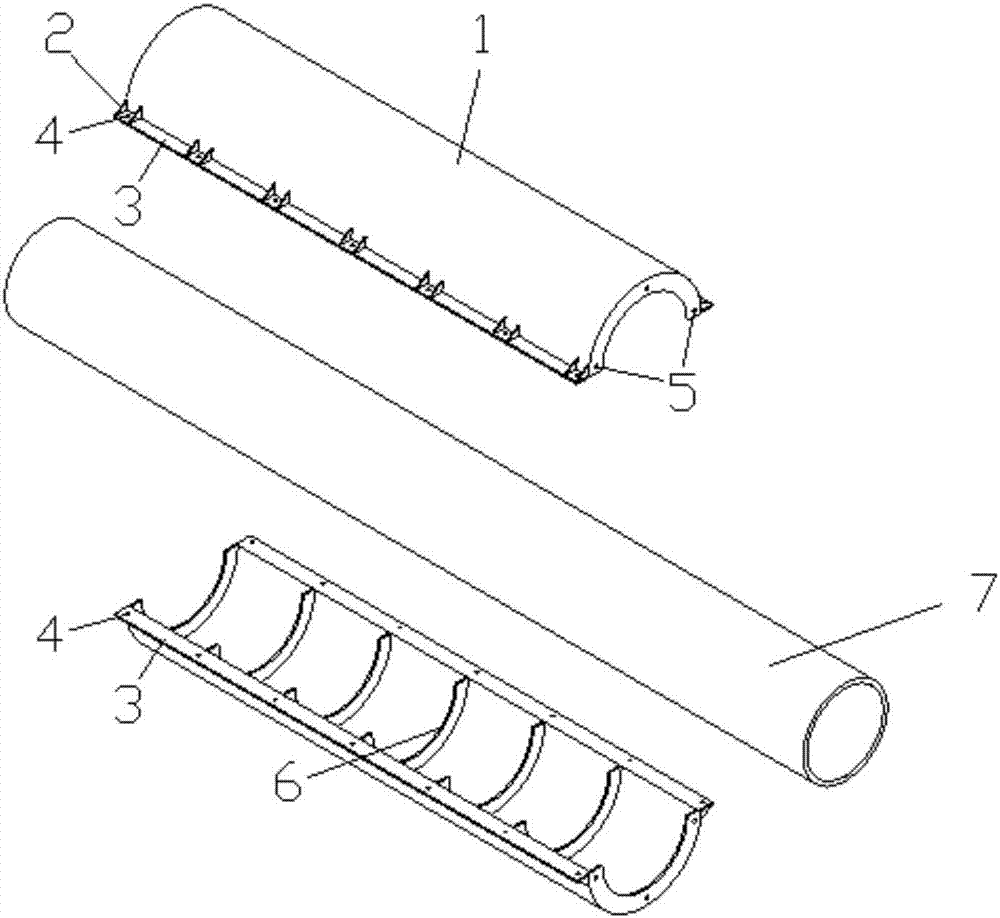
[0022] Such as figure 1 The reinforcement device for grid rods shown includes clamps that are symmetrical up and down, and the clamps include semicircular splints 1 , arc-shaped reinforcement plates 6 , connecting side plates 3 and stiffener plates 2 .

[0023] The arc-shaped reinforcing plates 6 are vertically welded on the inner side of the splint 1 at equal intervals along the axial direction of the splint 1, the connecting...


PUM


Abstract

The invention relates to a spatial grid member reinforcing device and a using method thereof. The spatial grid member reinforcing device comprises longitudinally-symmetrical clamps which can be combined together. Each clamp comprises a semicircular clamping plate, arc-shaped reinforcing plates, connecting side plates and reinforcing ribbed plates, wherein the arc-shaped reinforcing plates are perpendicularly fixed to the inner side of the clamping plate at equal intervals in the axial direction of the clamping plate, the connecting side plates are fixed to the two sides of the clamping plate, and the reinforcing ribbed plates are arranged at equal intervals in the length direction of the connection side plates and used for fixedly supporting the side plates and the clamping plate; and second bolt holes used for being connected with adjacent reinforcing devices are formed in the arc-shaped reinforcing plates at the two ends of the clamping plate. The using method of the spatial grid member reinforcing device comprises the following steps that the arc-shaped reinforcing plates are welded according the outer diameter of a reinforced member; the clamps are buckled to the two sides of the reinforced member; bolts are inserted into first bolt holes, and nuts are tightly screwed and fastened; and the reinforcing device is lengthened according to the length of the reinforced member. According to the spatial grid member reinforcing device and the using method thereof, under the condition that the stress states of the original member and an original structural system are not changed, the spatial grid member is reinforced, the bearing capacity of the spatial grid member is enhanced, construction safety is ensured, and the construction progress is also ensured.

Description

technical field [0001] The invention belongs to the technical field of network frame steel structure reinforcement, and in particular relates to a network frame bar reinforcement device and an application method thereof. Background technique [0002] At present, the large-span steel grid structure is widely used more and more, among which the grid structure form is a typical representative, which can meet the special structural requirements of super large area and super long span, and the application range is very wide. Grid structures usually have relatively long rods. When construction methods such as overall hoisting method, overall lifting (jacking) method, strip or block sliding method, and overall sliding method are used, some rods often cannot meet the requirements. To meet the load-bearing capacity requirements in the construction process, the usual practice is to replace such rods or weld stiffeners on the surface of such rods to strengthen them, but this often lead...

Claims


Application Information

Patent Timeline
Patent Type & Authority Applications(China)
IPC IPC(8): E04G23/02
CPCE04G23/0218
Inventor 韩向科殷永艺宋凯梁宏文
Owner SHANGHAI ERSHIYE CONSTR CO LTD
Learn More