Vertical mounting structure and vertical mounting method of permanent magnetic coupling, online separating and resetting method

A permanent magnet coupling and installation structure technology, applied in the field of mechanical transmission, can solve the problems of difficult separation, eccentric adsorption together, narrow space, etc., to reduce vibration and noise, avoid eccentric adsorption, and high installation efficiency.

Pending Publication Date: 2017-11-21
JIANGSU MAGNET VALLEY TECH
View PDF4 Cites 1 Cited by
  • Summary
  • Abstract
  • Description
  • Claims
  • Application Information

AI Technical Summary

Problems solved by technology

[0003] First, there is space for the wrench when bolts and other joints are tightened. Vertical motors often need to be supported by rotary supports such as sleeves. Because the internal space of rotary supports such as sleeves is small (basically no wrench space), the permanent magnet The shaft sleeve and shaft of the coupling are often installed with a shrink fit process, and the magnetic steel inside the permanent magnet coupling cannot withstand high temperatures. Therefore, the shaft sleeve and the driving rotor or driven rotor are also made of separate structures, so it is bound to Fasteners such as bolts are used for connection, and there is often no space for wrenches in vertical installation, which leads to problems related to the fastening of bolts on permanent magnet couplings.
[0004] Second, there is the problem of installation error. Rotary supports such as sleeves are often connected by bolts on the end face of the flange and the end face of the motor flange. The support has no guiding parts. The active rotor and driven rotor of the synchronous permanent magnet coupling are arranged There must be certain installation errors (radial and angular errors, etc.) during installation of permanent magnetic steel, so there will be uneven air gaps during installation, and even if there is a slight carelessness, the two permanent magnet rotors will be eccentrically adsorbed together, resulting in inseparable
One rotor of the asynchronous permanent magnet coupling is a permanent magnet rotor, and the other rotor is a metal conductor rotor. Although there is no problem of eccentric adsorption during installation, there is also the problem of uneven air gap after installation without guide parts, which leads to the inability to meet Transfer the maximum torque required
[0005] Third, the online separation and reset of vertical motors. For multi-motor combined drive systems, the existing technology cannot realize the online separation, maintenance and reset of vertical motors during the work process, which will seriously affect production for some important equipment.
[0006] Fourth, the torque cannot be adjusted. At present, the permanent magnet coupling often integrates the active rotor and the driven rotor, and the maximum transmitted torque value is often a certain value, and the demand for the maximum transmitted torque value cannot be adjusted appropriately according to the needs.

Method used


Image

  • Vertical mounting structure and vertical mounting method of permanent magnetic coupling, online separating and resetting method
  • Vertical mounting structure and vertical mounting method of permanent magnetic coupling, online separating and resetting method
  • Vertical mounting structure and vertical mounting method of permanent magnetic coupling, online separating and resetting method

Examples


Embodiment Construction

[0071] Specific embodiments of the present disclosure will be described in detail below in conjunction with the accompanying drawings. It should be understood that the specific embodiments described here are only used to illustrate and explain the present disclosure, and are not intended to limit the present disclosure.

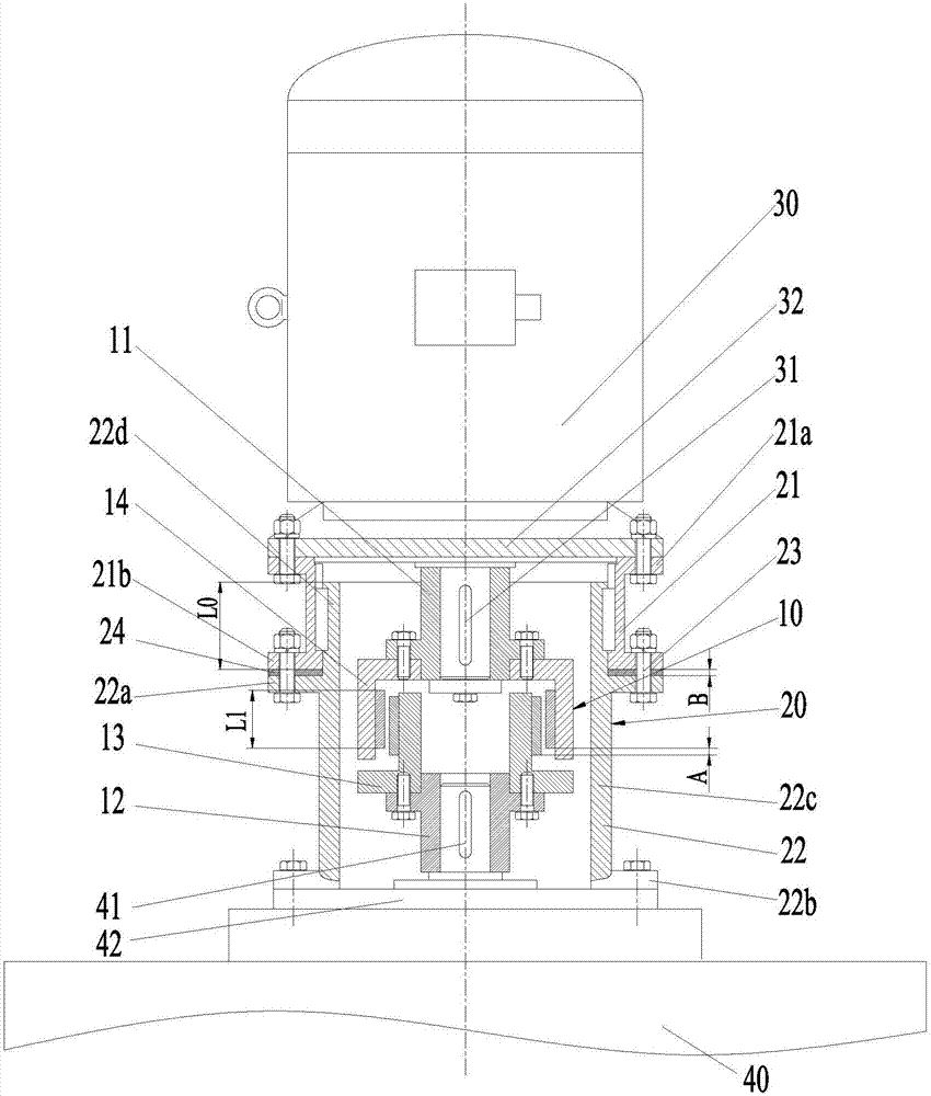
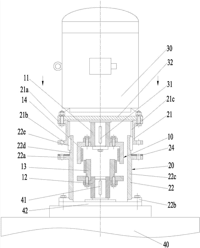
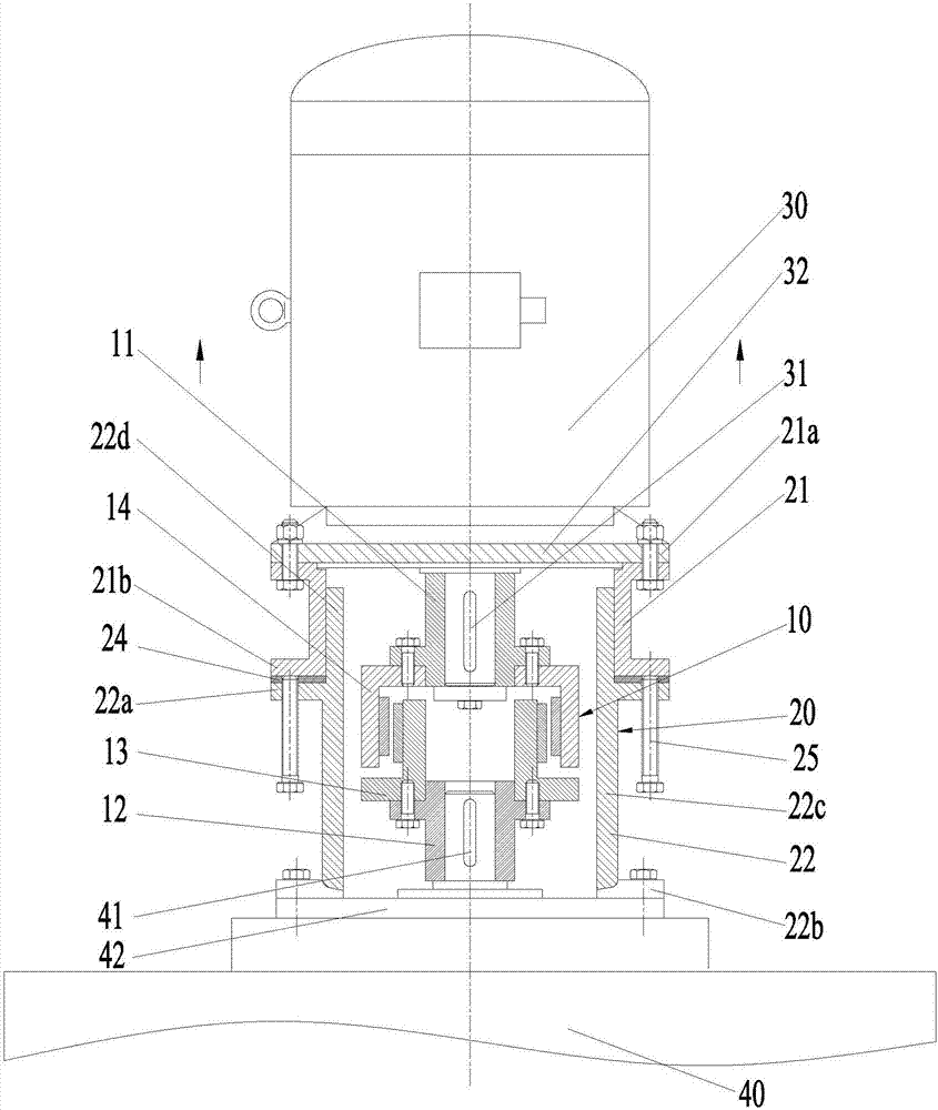
[0072] In the present disclosure, unless stated to the contrary, the used orientation words such as "up, down" usually refer to figure 1 shown above and below in the axial direction. A multi-motor linkage system refers to a system in which multiple motors are connected in parallel to provide power to the same load. Wherein, in the embodiment of the present invention, the load end 40 may be equipment such as a reducer.

[0073] Such as Figure 1 to Figure 3 As shown, the vertical installation structure of the permanent magnet coupling of the specific embodiment of the present invention includes a coaxially arranged permanent magnet coupling 10 and a support...


PUM


Abstract

The invention relates to a vertical mounting structure and a vertical mounting method of a permanent magnetic coupling, and an online separating and resetting method. The vertical mounting structure comprises a permanent magnetic coupling and a supporting sleeve which are coaxially arranged. One end of the supporting sleeve is connected with a vertical motor, and the other end is connected with a load end. The permanent magnetic coupling is arranged in the supporting sleeve. The permanent magnetic coupling comprises a first shaft sleeve, a second shaft sleeve, a driven rotor and an active rotor. The first shaft sleeve sleeves the output shaft of a vertical motor and is connected with the active rotor. The second shaft sleeve sleeves an input shaft at the load end and is connected with the driven rotor, wherein the supporting sleeve comprises a first sleeve and a second sleeve which are separately arranged and are detachably connected. The first sleeve is connected with the vertical motor, and the second sleeve is connected with the load end. The vertical mounting structure and the vertical mounting method have advantages of settling a problem of vertical mounting of the permanent magnetic coupling, realizing easy connection and separation, and realizing online separated maintenance and resetting of a faulted motor in a motor-motor linked system.

Description

technical field [0001] The present disclosure relates to the field of mechanical transmission, in particular to a vertical installation structure, a vertical installation method, and an online separation and reset method of a permanent magnet coupling. Background technique [0002] In the prior art, the connection between the vertical motor and the load end (such as the reducer end) generally needs to be transitioned through an integrally formed annular closed sleeve. One end of the sleeve is connected to the vertical motor through a flange, and the other end is also passed through The flange is connected to the load side. Due to the unique advantages of permanent magnetic coupling transmission, its application in mechanical transmission systems is more and more worthy of people's attention, but there must be some technical problems when the permanent magnetic coupling is directly applied to the vertical motor drive system in the prior art. question: [0003] First, there ...

Claims


Application Information

Patent Timeline
IPC IPC(8): H02K49/10H02K15/00
CPCH02K15/00H02K49/108
Inventor 徐俊峰牟红刚王文彤
Owner JIANGSU MAGNET VALLEY TECH
Why Eureka
Try Eureka