Non-bridge APFC active factor power correction circuit

A power correction and circuit technology, applied in the direction of output power conversion devices, electrical components, energy industry, etc., can solve problems such as difficult EMI certification, reduce common mode interference, reduce temperature rise, improve reliability and life Effect

Active Publication Date: 2017-11-21
GUANGDONG UNIV OF TECH
View PDF5 Cites 25 Cited by
  • Summary
  • Abstract
  • Description
  • Claims
  • Application Information

AI Technical Summary

Problems solved by technology

[0003] but figure 1 In the traditional bridgeless APFC circuit shown, the common mode interference of the negative pole of the output filter capacitor C, that is, the common potential reference point of the primary side is much larger than that of the traditional bridged APFC circuit, and it is not easy to pass EMI certification

Method used


Image

  • Non-bridge APFC active factor power correction circuit
  • Non-bridge APFC active factor power correction circuit
  • Non-bridge APFC active factor power correction circuit

Examples


Embodiment Construction

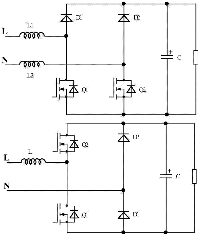
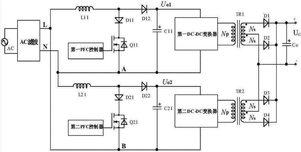
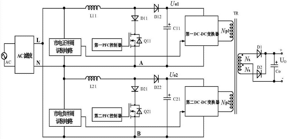
[0030] The core of the invention is to provide a bridgeless APFC active factor power correction circuit. Compared with the traditional bridgeless APFC circuit, the loss is further reduced and the electromagnetic interference is small.

[0031] In order to make the purpose, technical solutions and advantages of the embodiments of the present invention clearer, the technical solutions in the embodiments of the present invention will be clearly and completely described below in conjunction with the drawings in the embodiments of the present invention. Obviously, the described embodiments It is a part of embodiments of the present invention, but not all embodiments. Based on the embodiments of the present invention, all other embodiments obtained by persons of ordinary skill in the art without making creative efforts belong to the protection scope of the present invention.

[0032] The invention provides a bridgeless APFC active factor power correction circuit, comprising an AC po...


PUM


Abstract

The invention discloses a non-bridge APFC active factor power correction circuit which comprises an AC positive half cycle APFC circuit, an AC negative half cycle APFC circuit, and an AC filter circuit, wherein the AC positive half cycle APFC circuit comprises a first inductor, a first switch tube, a positive half cycle first diode, a positive half cycle second diode, a first capacitor, a first PFC controller and a first DC-DC converter as a load, and the AC negative half cycle APFC circuit comprises a second inductor, a second switch tube, a negative half cycle first diode, a negative half cycle second diode, a second inductor, a second PFC controller and a second DC-DC converter as a load. Compared with conventional non-bridge APFC circuit, the non-bridge APFC active factor power correction circuit has lower loss, and smaller electromagnetic interference.

Description

technical field [0001] The invention relates to the technical field of active factor power correction, in particular to a bridgeless APFC active factor power correction circuit. Background technique [0002] In the switching power supply, in order to reduce the distortion of the input current in order to obtain a high power factor PF, a power factor pre-adjustment stage based on Boost topology can be added after the rectifier bridge to form a bridged APFC circuit, which is characterized by EMI (Electromagnetic interference) is small and easy to control, but at any time there are three high-power components in the conduction state, and the loss is large, so that the output power is limited. When the output power is large, in order to reduce the loss of the APFC circuit and reduce the temperature rise of the converter, such as figure 1 In the bridgeless APFC circuit shown, in the bridgeless APFC circuit, only two high-power components are in the conduction state at any time, ...

Claims


Application Information

Patent Timeline
Patent Type & Authority Applications(China)
IPC IPC(8): H02M1/42H02M1/44H02M3/28
CPCH02M1/4258H02M1/44H02M3/28H02M1/0067H02M1/0054Y02B70/10Y02P80/10
Inventor 潘永雄李勇陈林海
Owner GUANGDONG UNIV OF TECH
Why Eureka
Try Eureka