SCR (selective catalytic reduction) flue gas denitration reactor

A denitrification reactor and reactor technology, applied in the field of flue gas denitrification, can solve problems such as unbalanced thermal expansion of the reactor, and achieve the effects of coping with high temperature of flue gas, solving unbalanced thermal expansion, and reducing abrasion

Active Publication Date: 2017-11-24
北京晨晰环保工程有限公司
View PDF4 Cites 0 Cited by
  • Summary
  • Abstract
  • Description
  • Claims
  • Application Information

AI Technical Summary

Problems solved by technology

[0005] The purpose of the present invention is to provide an SCR flue gas denitrification reactor, which optimizes and stabilizes the flue gas flow compared with the traditional SCR flue gas denitrification reactor, reduces the abrasion of the catalyst, effectively copes with the high temperature of the flue gas, and solves the problem of Technical problem of uneven thermal expansion of the reactor

Method used


Image

  • SCR (selective catalytic reduction) flue gas denitration reactor
  • SCR (selective catalytic reduction) flue gas denitration reactor
  • SCR (selective catalytic reduction) flue gas denitration reactor

Examples


Embodiment Construction

[0021] The specific implementation manners of the present invention will be further described below in conjunction with the accompanying drawings.

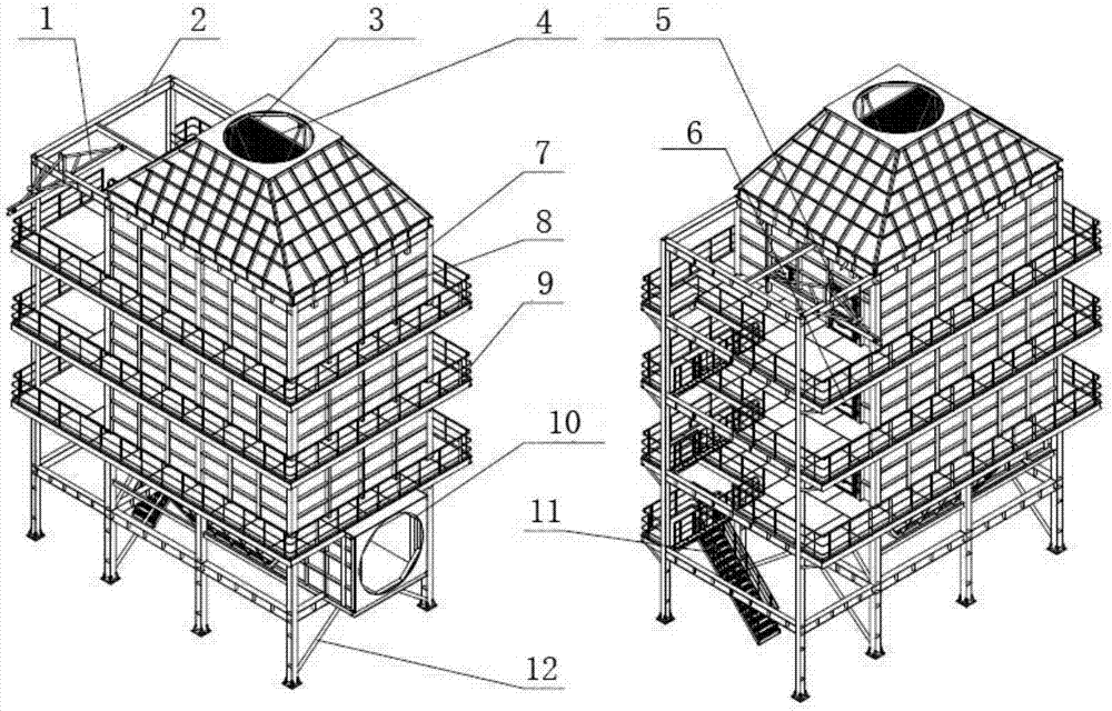
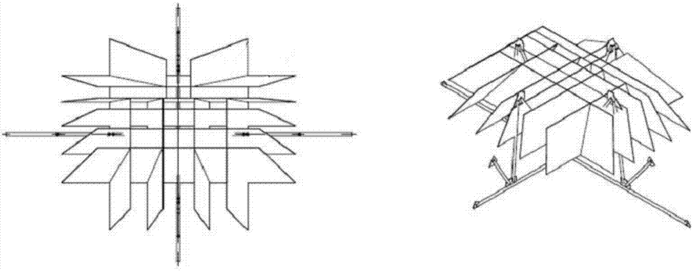
[0022] Exemplary SCR flue gas denitrification reactor of the present invention such as figure 1 As shown, it is vertical, filled with catalyst inside, including crane beam 1, beam 2, rectification grid 3, deflector plate 4 (15-40 pieces), catalyst transfer door 5, manhole door 6, column 7 (material It is alloy steel Q345B), wall plate 8, platform 9, flue assembly 10, inclined ladder 11, diagonal brace 12.

[0023] Columns 7 arranged in the vertical direction, beams 2 arranged in the horizontal direction, diagonal braces 11 connected between the columns 7 at the bottom for reinforcement, and wall panels 8 laid flat between the columns 7 and the beams 2 (for SCR method flue gas denitrification The reactor is sealed to isolate the external environment) to form the outer wall of the reactor, which is used to fix and protect the denit...


PUM


Abstract

The invention belongs to the technical field of flue gas denitration and relates to an SCR (selective catalytic reduction) flue gas denitration reactor. The denitration reactor filled with a catalyst is vertical and comprises an outer reactor wall used for sealing the denitration reactor, a flue gas inlet located in the top of the outer reactor wall, a flue assembly located on the lower portion of the outer reactor wall, a guide plate and a flow straightening grid; the guide plate and the flow straightening grid are located at the position of the flue gas inlet and in side the reactor; the guide plate is arranged to be three-dimensional. By the arrangement, flue gas in a flue is allowed to enter the denitration reactor uniformly; the flow straightening grid is in a grid form, welded by steel plates uniformly arranged and is used for integrating the flue gas entering the grid through collision; compared with a traditional SCR flue gas denitration reactor, the flue gas denitration reactor is optimized and can stabilize flow rate of the flue gas, the catalyst is less abraded, high temperature of the flue gas is effectively dealt with, and the technical problem that overall thermal expansion of the reactor is unbalanced is solved.

Description

technical field [0001] The invention belongs to the technical field of flue gas denitrification, and relates to a reactor for flue gas denitration by SCR method. Background technique [0002] Nitrogen oxides are one of the main sources of air pollution. 70% of my country's nitrogen oxide emissions come from the direct combustion of coal, and the power industry is a large coal-burning household in my country, so thermal power plants have become one of the main sources of nitrogen oxide pollution. With the further improvement of environmental protection standards, large-scale and medium-sized thermal power plants across the country have implemented large-scale denitrification projects, and denitrification has become one of the key funding directions for energy-saving and environmental protection industries during the "13th Five-Year Plan". There are three main denitrification technologies currently in use, among which Selective Catalytic Reduction (SCR) is the most advanced a...

Claims


Application Information

Patent Timeline
IPC IPC(8): B01D53/90B01D53/88B01D53/56
CPCB01D53/56B01D53/885B01D53/90B01D2258/0283
Inventor 张德生于立波张玉生
Owner 北京晨晰环保工程有限公司
Why Eureka
Try Eureka