
A vacuum cleaner for removing machining debris for laser precision machining

A technology of precision machining and vacuum cleaning, applied in metal processing equipment, laser welding equipment, manufacturing tools, etc., can solve the problems of scattered cleaning power, complicated airflow, damage to equipment and staff health, etc., to avoid pollution, Enhanced air tightness effect

Active Publication Date: 2019-04-09
BEIJING INST OF AEROSPACE CONTROL DEVICES
View PDF12 Cites 0 Cited by
  • Summary
  • Abstract
  • Description
  • Claims
  • Application Information

AI Technical Summary

Problems solved by technology

This method has very significant disadvantages: In order to expand the vacuuming window, the vacuum cleaner port uses a bell mouth structure, which disperses the power of vacuuming, and some heavy metal debris cannot be sucked into the vacuuming pipe, and the vacuuming is not thorough and cannot be removed. Micron-sized dust; the airflow near the suction port is complicated, and some debris will be blown by the convective airflow, causing pollutants and debris particles to diffuse into the working environment, damaging the health of equipment and staff
In addition, in order to ensure the airtightness of the vacuum chamber, there is generally a large contact pressure between the vacuum chamber and the workpiece of the vacuum device, and the force between the rotor and the stator of the high-speed rotating device is not allowed to exceed 1N, so this dust suction Method not suitable for high speed rotating devices

Method used


Image

  • A vacuum cleaner for removing machining debris for laser precision machining
  • A vacuum cleaner for removing machining debris for laser precision machining
  • A vacuum cleaner for removing machining debris for laser precision machining

Examples


Embodiment

[0041] A specific example of the present invention is described below in conjunction with accompanying drawing:

[0042] This example is mainly aimed at the laser precision deduplication system to remove processing debris, prevent the diffusion of pollutants and debris particles, and damage instruments and equipment, and is suitable for precision numerical control processing systems.

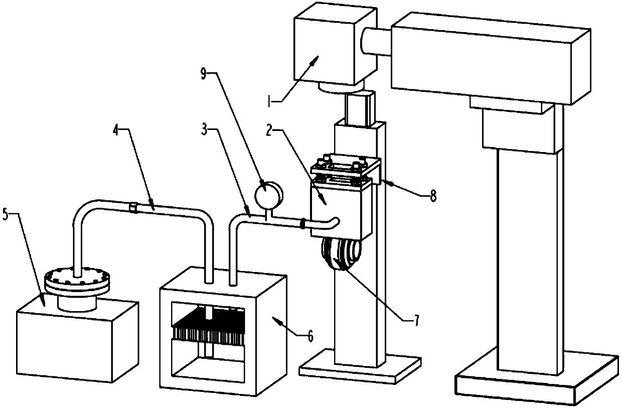
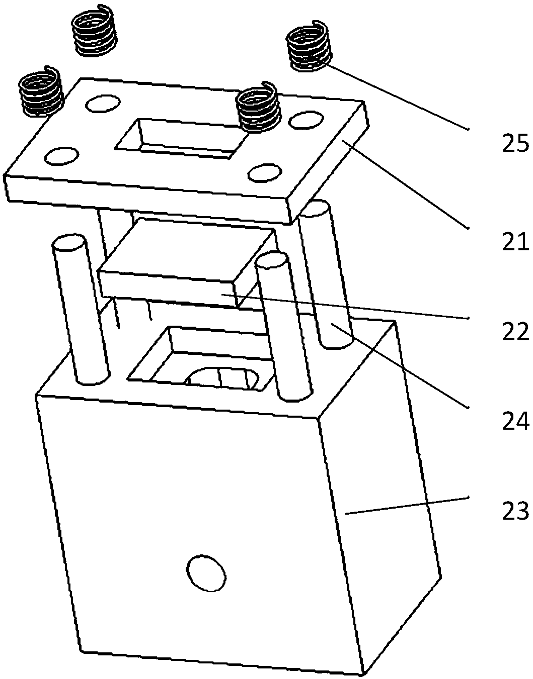
[0043] This example consists of a laser weight removal device (1), a vacuum cleaner (2), a front end dust suction pipe (3), a rear end dust suction pipe (4), a vacuum generator (5), a filter box (6) and a processing The workpiece (7) constitutes a laser dynamic balancing processing system. Use the MHX-02-007 model laser weight removal device (1) to remove the partial weight of the unbalanced rotor. The rotor is a metal structure entity with a complex shape with a maximum diameter of 34mm and a height of 25mm. When working, the laser de-weighting device emits laser light, removes the heavy part ...


PUM

PropertyMeasurementUnit
thicknessaaaaaaaaaa

Abstract

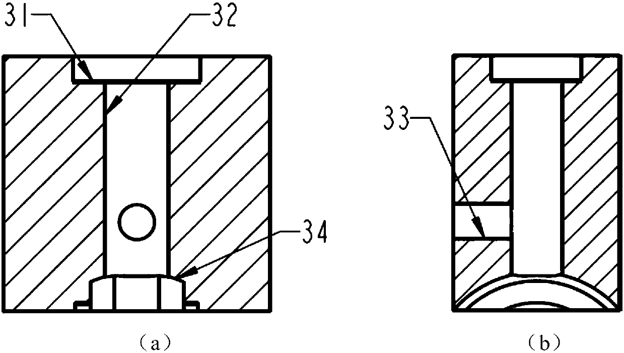
The invention relates to a vacuum dust absorption device used for removing machining chippings for precise laser machining. The vacuum dust absorption device comprises a dust cover and a vacuum pumping filter device. When the vacuum dust absorption device works, the contact face at the bottom end of the dust cover is attached to the to-be-machined portion of a to-be-machined workpiece, a laser emitted by a laser weight-removing device passes through anti-reflection glass and a vacuum cavity and then acts on the to-be-machined portion of the to-be-machined workpiece, weight removing is conducted on the to-be-machined workpiece, and dust generated in the weight-removing process is absorbed by the vacuum pumping filter device. A locally-surrounded dust absorption structure is put forward for the first time, a machining area is separated from a gap between a stator and a rotor of the workpiece so that a pollution source cannot enter the gap, pollution to the interior of the gap is avoided, the pressure of the contact face between the vacuum dust absorption device and the machining workpiece is small, and therefore it is guaranteed that no extra action force is generated between a stator and a rotor of a high-speed rotating device.

Description

technical field [0001] The invention relates to a vacuum cleaning device for precision machining to remove processing debris, which is used for a high-precision laser de-weighting system to realize the protection of pollutants and the blocking protection of micron-level particles, and belongs to the technical field of dust collection. Background technique [0002] With the continuous improvement of the precision and stability of high-speed rotating devices (such as air bearings, etc.), the precision and process requirements for rotor dynamic balance are also getting higher and higher. Dynamic balance is essentially accomplished by changing the mass distribution of the rotor. The laser dynamic balancing machine uses pulsed laser instead of mechanical drill to drill holes to remove the partial weight of the unbalanced rotor and complete the precise adjustment of the rotor's center of mass. The debris particles produced by pulsed laser drilling are small and low in weight, and ...

Claims


Application Information

Patent Timeline
Patent Type & Authority Patents(China)
IPC IPC(8): B23K26/142B23K26/36B23K26/70
CPCB23K26/142B23K26/36B23K26/702
Inventor 李本海薛亚飞王军龙李广李凯高文焱闫贝贝王学锋
Owner BEIJING INST OF AEROSPACE CONTROL DEVICES
Learn More