A method for on-site dynamic balancing of the high-speed output shaft of the reducing and sizing gearbox

An on-site dynamic balancing and output shaft technology, applied in the field of on-site dynamic balancing, can solve the problems of inconvenient application, cumbersome operation, inefficient practical effect, etc., and achieve the effect of convenient on-site application, avoiding potential safety hazards, and facilitating anti-loosening and tightening.

Active Publication Date: 2019-03-29
马鞍山马钢华阳设备诊断工程有限公司
View PDF7 Cites 0 Cited by
  • Summary
  • Abstract
  • Description
  • Claims
  • Application Information

AI Technical Summary

Problems solved by technology

[0006] The above applications are all helpful to achieve on-site dynamic balance, but the practical effect is not efficient. It often takes several times of debugging to achieve dynamic balance. The operation is cumbersome, and there are still many inconveniences in application.

Method used


Image

  • A method for on-site dynamic balancing of the high-speed output shaft of the reducing and sizing gearbox
  • A method for on-site dynamic balancing of the high-speed output shaft of the reducing and sizing gearbox
  • A method for on-site dynamic balancing of the high-speed output shaft of the reducing and sizing gearbox

Examples


Embodiment 1

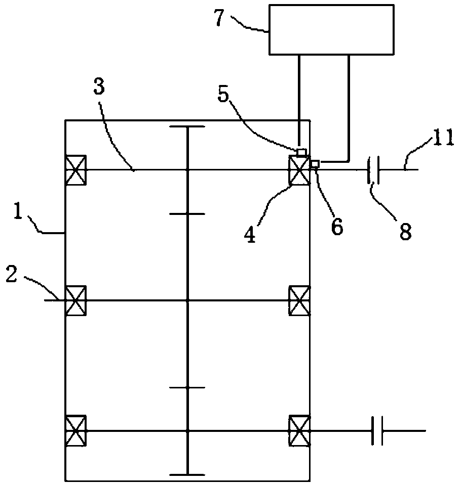
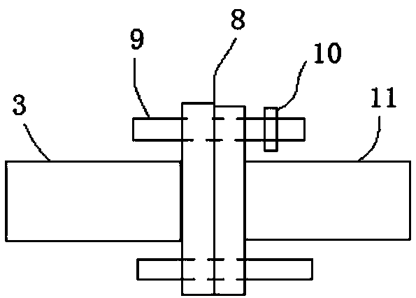
[0045] Such as Figure 1 ~ Figure 4 As shown, the reducing and sizing gearbox 1 is provided with an input shaft 2 and an output shaft 3, and the transmission between the input shaft 2 and the output shaft 3 is carried out through transmission gears, that is, both the input shaft 2 and the output shaft 3 are provided with gears, through Gear meshing transmission; the two ends of the output shaft 3 are fixed with bearing housings 4, the output end of the output shaft 3 is connected with the connecting shaft 11 through the coupling 8, and the connecting shaft 11 is finally connected to the rolling mill, specifically as figure 2 As shown, the coupling 8 includes two opposite flanges, and the bolt rod 9 passes through the two flanges for connection and is fastened by a nut (the nut is not shown in the figure). When used on site, the output shaft 3 is prone to excessive vibration during long-term operation, especially the problem of excessive axial vibration. After repeated inspect...

Embodiment 2

[0064] The on-site dynamic balancing method of a high-speed output shaft of a reducing and sizing gearbox in this embodiment is basically the same as that in Embodiment 1, except that the gamma value in this embodiment is 70°, and the safety factor k is 0.8.

Embodiment 3

[0066] The on-site dynamic balancing method of the high-speed output shaft of the reducing and sizing gearbox in this embodiment is basically the same as that in Embodiment 1, except that the gamma value in this embodiment is 80°, and the safety factor k is 0.9.


PUM


Abstract

The invention discloses a field dynamic balancing method for the high speed output shaft of a diameter reducing gear box, and belongs to the field of field dynamic balancing. The method includes the steps of 1, installing a key phase sensor and a vibration sensor, and connecting to a dynamic balance instrument; 2, reading the rotation speed n of the output shaft, the initial rotation frequency amplitude alpha and the initial phase value beta; 3, adding test mass block M at the beta + gamma phase position; 4, reading the rotation speed n1 of the output shaft, the rotation frequency amplitude alpha 1 and the phase value beta 1; 5, based on amplitude alpha, beta, test mass M, test mass M phase beta + gamma, alpha 1 and beta 1, calculating strain addition mass m1 and phase delta beta; 6, reading the rotation speed n2, the rotation frequency amplitude alpha 2 and the phase value beta 2, confirming whether or not static balance is required, and if yes, repeating the above steps. The field dynamic balancing method overcomes the disadvantage that the output shaft of the diameter reducing gear box produces unbalance easily to affect the stable use of the field, and can quickly and effectively reduce the problem that the axial vibration of the output shaft of the diameter reducing gear box is high, so that the disassembly of a speed change gear box can be reduced, and the cost of dynamic balance can be reduced.

Description

technical field [0001] The invention relates to the technical field of on-site dynamic balancing, and more specifically relates to a method for on-site dynamic balancing of a high-speed output shaft of a reducing and sizing gearbox. Background technique [0002] With the development of the current manufacturing industry, the demand for high-speed gearboxes is increasing. No matter how high the process and machining accuracy are, the shafts in the gearbox will always have unbalance. As long as the unbalance is controlled within a certain range, it will not be damaged. The normal operating conditions of the gearbox will be affected; but once the unbalance exceeds a certain limit, it will have a greater impact on the normal operating conditions of the gearbox, and in severe cases, major accidents will occur. Therefore, dynamic balance is a basic problem that must be solved in the manufacturing process of high-speed gearboxes. The unbalance affects the vibration of the gear sha...

Claims


Application Information

Patent Timeline
Patent Type & Authority Patents(China)
IPC IPC(8): G01M1/38
CPCG01M1/28G01M1/32
Inventor 刘健张国新王顺利贾维龙简彦成汪江涛
Owner 马鞍山马钢华阳设备诊断工程有限公司
Why Eureka
Try Eureka