
Mine filling material compression characteristic experiment device and experiment method thereof

An experimental device and compression characteristics technology, applied in the direction of measuring devices, analysis materials, strength characteristics, etc., can solve the problems of ignoring the friction effect, not suitable for tailings, and not considering the compression characteristics of cemented filling body, etc., and achieve the effect of simple structure

Active Publication Date: 2017-11-24
CENT SOUTH UNIV
View PDF8 Cites 14 Cited by
  • Summary
  • Abstract
  • Description
  • Claims
  • Application Information

AI Technical Summary

Problems solved by technology

[0003] Chinese patent CN203053782U and Chinese patent CN105181463A respectively disclose a gangue filling experimental compression mold, a water-containing gangue compression experimental device and its experimental method, which are mainly aimed at testing the compression characteristics of dry gangue and water-containing gangue during dry filling in coal mines. However, the mine filling process also includes water-sand filling and cemented filling. The above-mentioned technical scheme is not suitable for filling materials such as tailings in metal mines, and does not consider the compression characteristics of early-age cemented filling bodies under the action of cementing materials. Friction Effects Caused by Confining Pressure During Limited Compression

Method used


Image

  • Mine filling material compression characteristic experiment device and experiment method thereof
  • Mine filling material compression characteristic experiment device and experiment method thereof
  • Mine filling material compression characteristic experiment device and experiment method thereof

Examples


Embodiment

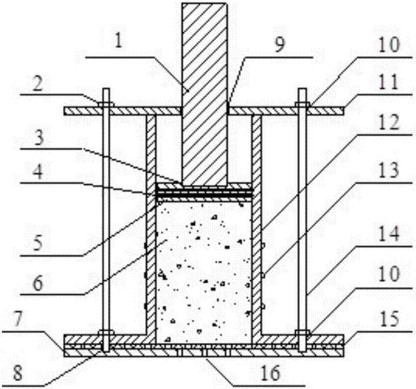
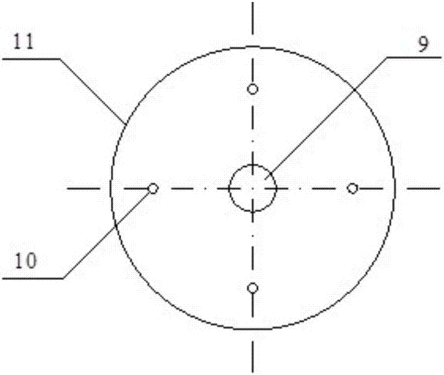
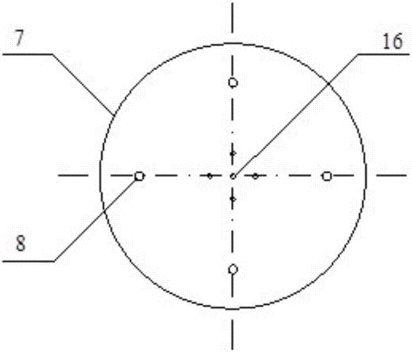
[0049] see Figure 1-6 , a mine filling material compression characteristic experiment device in the illustration is the preferred solution of the present invention, which specifically includes a circular pressure bearing column 1, a nut 2, a sealing ring 4, a piston 5, a bottom cover 7, a top cover 11, a belt chassis Steel cylinder 12, hoop strain gauge 13, screw rod 14, geotextile 15 and other components.

[0050] Wherein, the bottom cover 7, the top cover 11 and the steel cylinder 12 with a chassis form a cavity for filling the filling material 6, and the main body of the cavity is a cylindrical inner chamber with a steel cylinder 12 with a chassis, and the bottom of the steel cylinder 12 with a chassis and The bottom cover 7 is equipped with a bleeding structure to ensure the water discharge of the filling material during the compression process. The top is fixed to the top cover 11, and a piston 5 is installed in the inner cavity of the steel cylinder. The inner wall of ...


PUM

PropertyMeasurementUnit
Apertureaaaaaaaaaa
Hole depthaaaaaaaaaa
Diameteraaaaaaaaaa

Abstract

The invention discloses a mine filling material compression characteristic experiment device and an experiment method thereof. The experiment device is arranged on a pressure machine, and comprises a cavity for holding a filling material, wherein a bleeding structure is arranged at the bottom end of the cavity; the other end of the cavity is sealed through a slidable piston in the cavity; the bottom end of the cavity is arranged on a lower pressure-bearing plate of the pressure machine; a pressure-bearing column connected with the piston contacts an upper pressure-bearing plate of the pressure machine; an outer wall of the cavity is provided with a plurality of hoop strain foils at different axial positions in a pasting way; the hoop strain foils are connected with a statical strain indicator; a displacement sensor is also arranged between the upper pressure-bearing plate and the lower pressure-bearing plate of the pressure machine; the statical strain indicator and the displacement sensor are in signal connection with a computer connected with a pressure machine measuring system. The mine filling material compression characteristic experiment device provided by the invention can be used for monitoring compression amounts of the filling materials under different stresses and a strain level of an outer wall of a steel cylinder through the pressure machine measuring system, and is simple in structure, convenient to operate, and applicable to compression characteristic tests of dry filling bodies, water sand filling bodies, cemented filling bodies and other filling bodies.

Description

technical field [0001] The invention belongs to the field of mine filling and mining, and in particular relates to an experimental device for compression characteristics of mine filling materials and an experimental method thereof. Background technique [0002] The filling mining method not only has high safety, but also can effectively reduce ore loss, dilution and solve tailings stacking and pollution problems. It is also beneficial to mine air leakage, heat damage, rock burst, ore spontaneous combustion, coal and gas outburst and other disasters The prevention and control of it is widely used in various mines at present. The compression characteristics of filling materials affect the movement and deformation of stope surrounding rocks, and are important assessment indicators for mine filling quality. The greater the compression rate of the filling body, the greater the movement range of the rock formation and the longer the stable period, which is more unfavorable to the...

Claims


Application Information

Patent Timeline
IPC IPC(8): G01N3/08G01N3/02G01N3/06
Inventor 吴浩赵国彦陈英代俊成梁伟章张海云
Owner CENT SOUTH UNIV
Learn More