Crack detection method based on laser scanning thermal imaging

A crack detection and thermal imaging technology, which is applied in the crack detection field of laser thermal imaging, can solve the problems of difficult detection of tiny cracks and low signal-to-noise ratio of materials with low thermal conductivity, so as to improve the signal-to-noise ratio of crack imaging and reduce the results Interference, take advantage of the full effect

Active Publication Date: 2017-11-24
CHINA JILIANG UNIV
View PDF4 Cites 20 Cited by
  • Summary
  • Abstract
  • Description
  • Claims
  • Application Information

AI Technical Summary

Problems solved by technology

[0006] The purpose of the present invention is to solve the problem that the signal-to-noise ratio of materials with low thermal conductivity is not high and the detection of micro-cracks is difficult by the above-mentioned existing laser scanning thermal imaging data processing method

Method used


Image

  • Crack detection method based on laser scanning thermal imaging
  • Crack detection method based on laser scanning thermal imaging
  • Crack detection method based on laser scanning thermal imaging

Examples


Embodiment Construction

[0024] In order to make the purpose of the present invention, technical solutions and advantages clear, the present invention will be further described below in conjunction with the accompanying drawings:

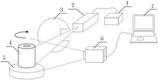
[0025] The detection system of the first embodiment of the present invention is as figure 2 As shown, the experimental object is a cylindrical ferrite device with a diameter of 19 mm, which may produce tiny cracks that are difficult for human eyes to detect due to material and process problems during the production process.

[0026] The detection system includes a laser 1 and its attached probe 2 , a laser shutter 3 , a sample rotating device 5 , an infrared thermal imager 6 , and a computer 7 . The laser 1 is used to scan and heat the cylindrical test piece 4; the laser shutter 3 is used to absorb the laser energy during the laser light preheating stage, so that the laser power can be stabilized; the sample rotating device 5 is used to make the laser and the cylinder unde...


PUM


Abstract

The invention discloses a crack detection method based on laser scanning thermal imaging. The method comprises the following steps: scanning a heated sample surface by relative movement of the line laser and the sample; adopting a thermal imager for recording the condition of temperature change of the sample surface in real time; adopting a computer for acquiring the heat signals on all the points of the sample surface according to the temperature distributions at different moments in a thermal image, aligning the time axis of the heat signals and cutting and then adopting an adjacent heat signal comparing method for imaging the cracks. According to the invention, the signal-to-noise ratio of the crack detection can be effectively promoted and tiny cracks on the detected piece surface can be detected.

Description

technical field [0001] The invention relates to a non-destructive detection method for cracks, which is used for detecting surface discontinuity of a plane or cylindrical measured piece, in particular to a crack detection method for laser thermal imaging. Background technique [0002] Cracks are one of the most important types of hazards in material structures. The cracks on the surface of the material are relatively small in size in the early stage, and they can be detected early to prevent the further development of cracks, which can effectively avoid major economic losses. [0003] Compared with traditional crack detection methods such as magnetic particle testing, machine vision, penetrant testing, and eddy current testing, laser thermal imaging technology has unique advantages. High sensitivity for very small crack detection, long-distance non-contact detection of the tested part, precise control of laser energy density and position, clear and intuitive imaging of micr...

Claims


Application Information

Patent Timeline
Patent Type & Authority Applications(China)
IPC IPC(8): G01N25/72
Inventor 侯德鑫叶树亮
Owner CHINA JILIANG UNIV
Why Eureka
Try Eureka