
Diesel engine single pump with high oil suction capacity

A diesel engine and unit pump technology, which is applied in mechanical equipment, engine components, fuel injection pumps, etc., can solve problems such as unstable fuel injection, short valve stem movement distance, and high noise, so as to avoid unstable fuel injection and reduce product quality. Cost, effect of high oil absorption capacity

Pending Publication Date: 2017-11-28
成都威特电喷有限责任公司
View PDF10 Cites 2 Cited by
  • Summary
  • Abstract
  • Description
  • Claims
  • Application Information

AI Technical Summary

Problems solved by technology

Due to the need for fast action of the valve stem, the movement distance of the valve stem is generally short, resulting in a small opening of the cone valve and a small flow area.
During the oil suction process of the unit pump, the plunger moves downward, and the fuel will form a high flow velocity and negative pressure at the cone valve, and cavitation will occur, causing the fuel to generate bubbles. The generation and disappearance of the bubbles is unstable, resulting in The fuel injection is unstable, which affects the running stability of the engine, and has the disadvantages of high fuel consumption, high noise and poor emission

Method used


Image

  • Diesel engine single pump with high oil suction capacity
  • Diesel engine single pump with high oil suction capacity
  • Diesel engine single pump with high oil suction capacity

Examples


Embodiment Construction

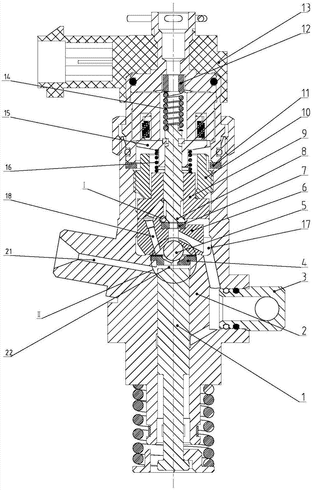
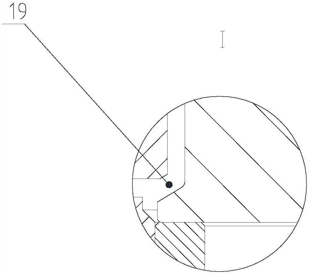
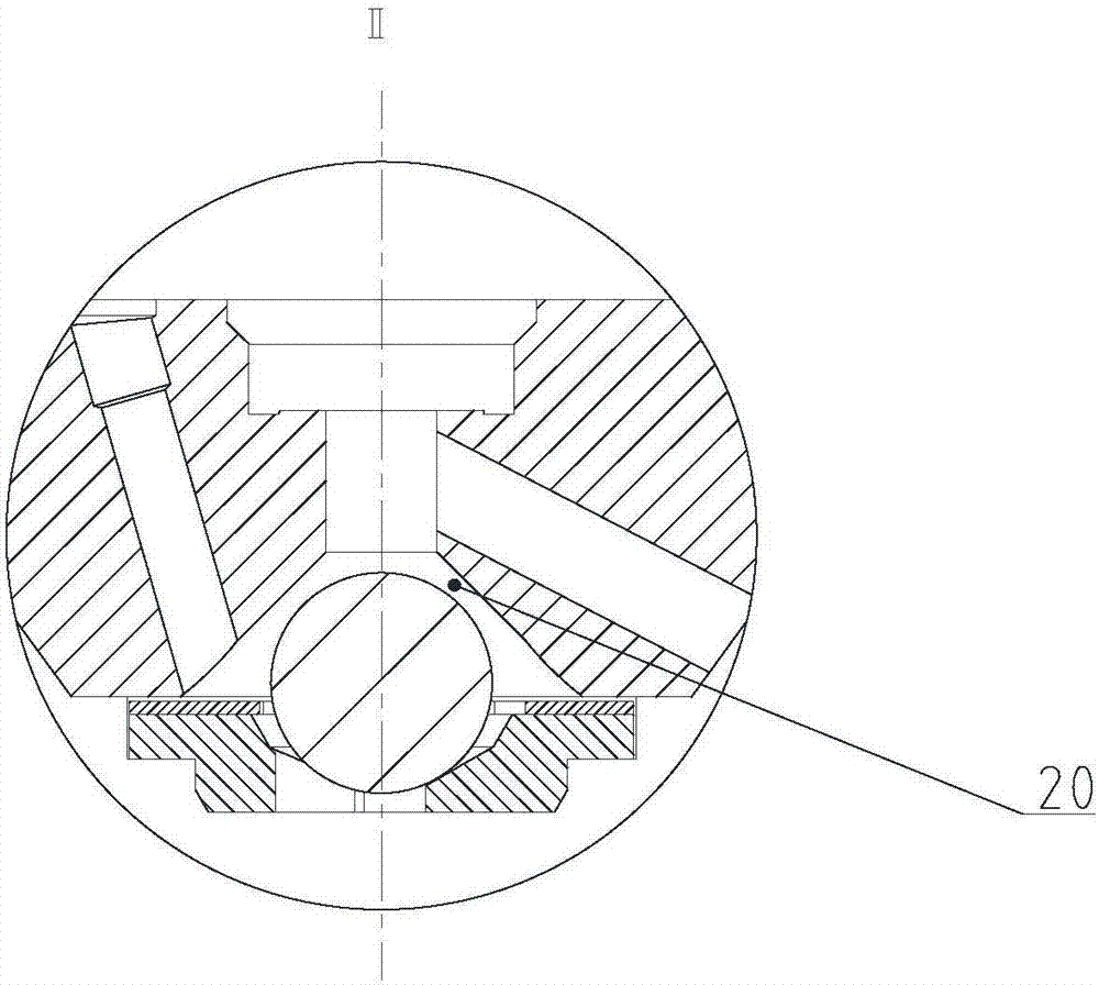
[0011] refer to figure 1 , figure 2 , image 3 . In the embodiment described below, a high oil-absorbing diesel engine unit pump has an electronically controlled unit pump body 2 and assembly of an electromagnet 13 that is powered under the control of the diesel engine ECU to attract the armature 15 to move upward. On the upper valve seat 9 on the pump body 2 , the valve stem 8 assembled in the upper valve seat 9 and the sealing ball 5 seated between the limit ball seat 4 and the lower valve seat 6 . The cylindrical surface of the valve stem 8 has the same diameter as the central hole of the upper valve seat 9 to form a sealing surface; the conical surface of the shaft end of the necking section of the valve stem 8 goes up and fits with the inner conical surface of the lower port of the upper valve seat 9 to form a sealing surface, and goes down to form a sealing surface. Stem necking oil channel 19; the lower valve seat 6 located below the conical surface of the shaft end...


PUM


Abstract

The invention discloses a diesel engine single pump with a high oil suction capacity, and aims to provide a single pump capable of improving the flow area of an oil suction channel and the oil suction capacity. The invention is realized through the following technical scheme that a lower valve seat is located below a conical surface of the shaft end of a valve rod; a high-pressure oil channel communicating with a conical valve hole and a low-pressure oil channel communicating with a central channel are formed in the lower valve seat; when a plunger goes downward, the volume of a plunger cavity is increased, the pressure of fuel oil in the plunger cavity is reduced, a sealing ball is separated from the conical valve hole, and a large-area circulating oil inlet channel is formed; the fuel oil flows into the plunger cavity from an oil inlet connector through the low-pressure oil channel, the conical valve hole and a central hole of a limiting ball seat; when the plunger goes upward, the volume of the plunger cavity is decreased, the pressure of the fuel oil is increased, the conical valve hole is closed by the sealing ball, and the fuel oil is prevented from flowing to the low-pressure oil channel (17) from the conical valve hole; and the fuel oil in the plunger cavity is forced only to flow to the oil inlet connector from the high-pressure oil channel through a valve rod neck oil path channel formed at a valve rod neck section and the low-pressure oil channel. Therefore, the problem that the flow area of the oil suction channel is small is solved.

Description

technical field [0001] The invention relates to an electronically controlled fuel injection device for a diesel engine. Background technique [0002] The electronically controlled unit pump for diesel engine has the advantages of high fuel injection pressure, flexible control of fuel injection quantity and fuel injection timing, and small modification of fuel injection system. It has a strong application prospect in the field of high-power diesel engines. Diesel engine electronically controlled unit pump refers to one cylinder and one oil pump, and the oil pump refers to high-pressure oil pump, or fuel injection pump. Unit pump UPS (UnitPumpSystem) belongs to single plunger pump system (independent injection system), each cylinder corresponds to a plunger type fuel injection pump, which can precisely control the fuel injection quantity injected into each cylinder. The high-pressure pump of the unit pump and the fuel injector assembly are connected through a very short high-...

Claims


Application Information

Patent Timeline
Patent Type & Authority Applications(China)
IPC IPC(8): F02M59/46
CPCF02M59/466
Inventor 吴波胡逍宇唐仁宏
Owner 成都威特电喷有限责任公司
Learn More