Metal-smelting heat-preserving furnace

A heat preservation furnace and metal technology, applied in the direction of furnaces, crucible furnaces, furnace components, etc., can solve the problems of short service life, high thermal stress load on the surface of heating elements, high frequency of maintenance or replacement, etc., achieve high heat utilization rate, prevent heat The effect passed to the shell

Active Publication Date: 2017-11-28
南通高新工业炉有限公司
View PDF5 Cites 0 Cited by
  • Summary
  • Abstract
  • Description
  • Claims
  • Application Information

AI Technical Summary

Problems solved by technology

[0002] Aluminum alloy melting and holding furnace is a new type of high-efficiency energy-saving aluminum melting furnace developed according to the aluminum smelting process. It is mainly used for melting and heat preservation of aluminum ingots. It can well meet the aluminum smelting process. The furnace is composed of melting furnace, Crucible, heating element, furnace cover lifting mechanism, electrical automatic temperature control system, etc. The furnace shell is welded into a cylindrical shape by section steel and steel plate, and there is a hole in the lower part of the front end of the furnace body, for the crucible to leak due to corrosion and oxidation. Under normal circumstances, the melt in the crucible can flow out of the furnace body through this hole, so that the furnace chamber of the working room will not be damaged; while the heating element structure in the existing aluminum alloy melting furnace is generally a strip-shaped heating sheet bent into a ring However, it is placed in the partition brick on the inner wall of the furnace and covered outside the crucible. Although the heating element of this structure has a large power, it is easy to cause problems such as high thermal stress load on the surface of the heating element, short service life, and high frequency of maintenance or replacement.

Method used


Image

  • Metal-smelting heat-preserving furnace
  • Metal-smelting heat-preserving furnace

Examples


Embodiment Construction

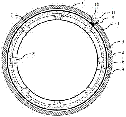
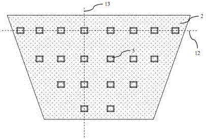
[0019] see figure 1 , the metal smelting and holding furnace of the present invention has a cylindrical furnace body structure, and the furnace body includes an outermost shell 1, a refractory brick layer 2 located in the shell 1 and an innermost crucible 6, and the shell There is a vacuum isolation cavity 4 between the body 1 and the refractory brick layer 2, the inner surface of the refractory brick layer 2 has a plurality of protrusions 5, and the plurality of protrusions 5 are in close contact with the crucible 6, the A first heating element 7 is arranged in the refractory brick layer 2, and the first heating element 7 is a spiral electric heating wire; each of the plurality of protrusions 5 has an independent second electric heating element 8, and the first heating element 7 The control circuits of the second electric heating element 8 and the first electric heating element 7 are independent of each other; the outer side of the refractory brick layer 2 is also wrapped wit...


PUM


Abstract

The invention provides a metal-smelting heat-preserving furnace. The metal-smelting heat-preserving furnace is provided with a cylindrical furnace body structure, wherein the furnace body comprises a housing at the outermost side, a refractory brick layer positioned in the housing and a crucible at the innermost side, wherein a vacuum insulating cavity is arranged between the housing and the refractory brick layer; a plurality of bumps are arranged on the inner surface of the refractory brick layer; the bumps are in tight contact with the crucible; a first heating element is arranged in the refractory brick layer, and the first heating element is a spiral electric heating wire; each of the bumps is provided with an independent electric heating element; the second electric heating elements are mutually independent from a control circuit of the first electric heating element; the second heating elements guide out electrode terminals through heat-resistant conductive rods; the heat-resistant conductive rods pass through one part of the refractory brick layer, the vacuum isolating cavity and the housing, and the electrode terminals are externally connected with control circuits for controlling working states of the second heating elements; the bumps are distributed in the form of an array, and part of the second electric heating elements can be electrically heated selectively.

Description

technical field [0001] The invention relates to the field of processing metal alloy raw materials, in particular to a metal smelting and holding furnace. Background technique [0002] Aluminum alloy melting and holding furnace is a new type of high-efficiency energy-saving aluminum melting furnace developed according to the aluminum smelting process. It is mainly used for melting and heat preservation of aluminum ingots. It can well meet the aluminum smelting process. The furnace is composed of melting furnace, Crucible, heating element, furnace cover lifting mechanism, electrical automatic temperature control system, etc. The furnace shell is welded into a cylindrical shape by section steel and steel plate, and there is a hole in the lower part of the front end of the furnace body, for the crucible to leak due to corrosion and oxidation. Under normal circumstances, the melt in the crucible can flow out of the furnace body through this hole, so that the furnace chamber of th...

Claims


Application Information

Patent Timeline
Patent Type & Authority Applications(China)
IPC IPC(8): F27B14/04F27B14/10F27B14/14F27D1/04
CPCF27B14/04F27B14/10F27B14/14F27B2014/045F27D1/04
Inventor 王如卿
Owner 南通高新工业炉有限公司
Why Eureka
Try Eureka