Z-segmented RF coil for MRI with gap and RF screen element

A coil and gap technology, applied in the field of medical systems and medical equipment, can solve problems such as reducing the image quality of MR imaging systems

Inactive Publication Date: 2017-11-28
KONINKLJIJKE PHILIPS NV
View PDF12 Cites 5 Cited by
  • Summary
  • Abstract
  • Description
  • Claims
  • Application Information

AI Technical Summary

Problems solved by technology

In addition, the connection of these sensors may require wiring, which may interfere with the field generated by the MR imaging system, reducing the image quality of the MR imaging system

Method used


Image

  • Z-segmented RF coil for MRI with gap and RF screen element
  • Z-segmented RF coil for MRI with gap and RF screen element
  • Z-segmented RF coil for MRI with gap and RF screen element

Examples


Embodiment Construction

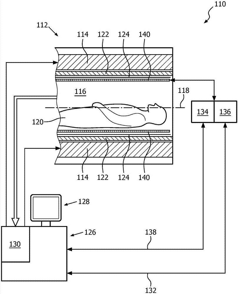
[0090] figure 1 A schematic illustration of a portion of an embodiment of a magnetic resonance (MR) imaging system 110 including an MR scanner 112 is shown. The MR imaging system 110 is generally described herein as the basis for all further embodiments.

[0091] The MR imaging system 110 includes a main magnet 114 provided for generating a static magnetic field. The main magnet 114 has a central bore that provides an examination space 116 about a central axis 118 for an object of interest 120 , typically a patient to be positioned therein. In this embodiment, the central bore and thus the static magnetic field of the main magnet 114 has a horizontal orientation according to the central axis 118 . In alternative embodiments, the orientation of the main magnet 114 may be different, for example, to provide a static magnetic field with a perpendicular orientation. Additionally, the MR imaging system 110 includes a magnetic gradient coil system 122 provided to generate a gradie...


PUM


Abstract

The present invention provides a radio frequency (RF) coil (140) for applying an RF field to an examination space (116) of a magnetic resonance (MR) imaging system (110) and / or for receiving MR signals from the examination space (116), whereby the RF coil (140) is provided having a tubular body (142), the RF coil (140) is segmented in a longitudinal direction (154) of the tubular body (142) into two coil segments (146), and the two coil segments (146) are spaced apart from each other in the longitudinal direction (144) of the tubular body (142), whereby a gap (148) is formed between the two coil segments (146). The present invention further provides a magnetic resonance (MR) imaging system (110) comprising at least one radio frequency (RF) coil (140) as specified above. The present invention still further provides a medical system (200) comprising the above magnetic resonance (MR) imaging system (110) and a medical device (202), which is arranged to access to the examination space (116) of the magnetic resonance (MR) imaging system (110) through the gap (148) of the RF coil (140). Even further, the present invention provides a method for applying a radio frequency (RF) field to an examination space (116) of a magnetic resonance (MR) imaging system (110), comprising the steps of providing at least one above radio frequency antenna device (140), and commonly controlling the two RF coil segments (146) to provide a homogenous B1 field within the examination space (116), in particular within the gap (148).

Description

technical field [0001] The present invention relates to a radio frequency (RF) coil for use in an examination space of a magnetic resonance (MR) imaging system, a magnetic resonance imaging system employing at least one such RF coil, the use of such an MR imaging system Medical system and medical device, and a method for applying a radiofrequency field to an examination volume of a magnetic resonance imaging system. Background technique [0002] State-of-the-art magnetic resonance (MR) imaging systems are, for example, magnetic resonance imaging systems with a magnetic field strength of 3 Tesla. This state-of-the-art MR imaging system employs, for example, a dual-channel radio frequency (RF) body coil that uses two geometrically decoupled feed positions of the bird cage for RF shimming. This technique provides high field uniformity and enables clinical imaging for other applications of high field strength. Although such MR imaging systems provide good imaging results, addi...

Claims


Application Information

Patent Timeline
Patent Type & Authority Applications(China)
IPC IPC(8): G01R33/34G01R33/3415G01R33/345G01R33/36G01R33/422A61B5/055
CPCA61B5/055G01R33/34076G01R33/3415G01R33/3453G01R33/365G01R33/422A61B5/704G01R33/345
Inventor C·洛斯勒C·芬德科里
Owner KONINKLJIJKE PHILIPS NV
Why Eureka
Try Eureka