Particulate matter trapping device

A particle and shell technology, applied in the direction of external electrostatic separator, electrostatic separation, etc., can solve secondary pollution and other problems, achieve the effect of low air resistance, large air flow, and reduce secondary pollution

Active Publication Date: 2017-12-01
JIANGSU ZHONGKE RUISAI POLLUTION CONTROL ENG
View PDF6 Cites 2 Cited by
  • Summary
  • Abstract
  • Description
  • Claims
  • Application Information

AI Technical Summary

Problems solved by technology

The principle of this method is generally to charge the particles through a high-voltage ionization device, so that the charged particles enter the electrostatic field, such as a parallel plate electric field, because the opposite charges attract each other, so the charged particles are adsorbed on the electrode opposite to its polarity on the board, so as to achieve the filtration of particles, but this method will have a serious problem of secondary pollution. After the charged particles are captured by the electrostatic field, the charged particles are neutralized, and with the flow of air, they are released again air out

Method used


Image

  • Particulate matter trapping device
  • Particulate matter trapping device
  • Particulate matter trapping device

Examples


Embodiment 1

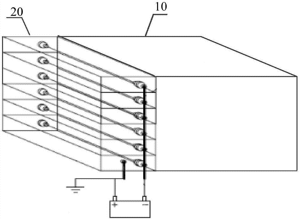
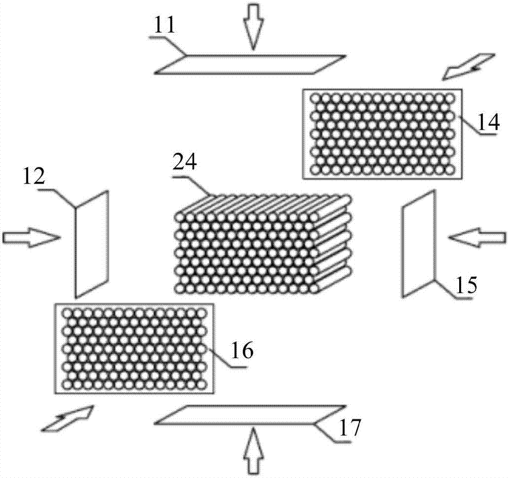
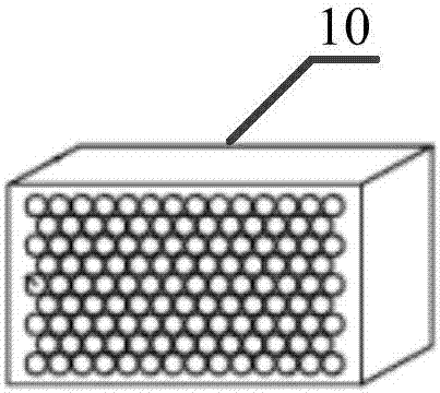
[0029] figure 1 It is a schematic structural diagram of a particulate matter trapping device provided in Embodiment 1 of the present invention, which can be used to trap particulate matter in gas, and the device specifically includes: a filter brush ( figure 1 not shown), housing 10 and gas ionization device 20, wherein,

[0030] The air inlet surface of the casing 10 runs through several through holes to the air outlet surface of the casing 10, and filter brushes are inserted one by one in the through holes, and the filter brushes are in contact with the side walls of the corresponding through holes. The casing 10 is made of conductive metal, and the filter brushes Including piezoelectric materials, the gas ionization device 20 is installed on the air intake surface of the housing 10, and the air flows through the gas ionization device 20 to charge the particles in the air flow and then pass through the through hole. When the air flows through the through hole, the air will ...

Embodiment 2

[0047] This embodiment is further optimized on the basis of the foregoing embodiments. In this embodiment, the filter brush includes a brush rod and brush filaments, and the brush filaments are fixed around the brush rod, so that after the charged particles enter the corresponding through holes, there are brush filaments in all directions to block and enhance the collection. Particle effect.

[0048] In the above solution, optionally, the brush rod is made of conductive metal, and the brush wire is made of piezoelectric material.

[0049] In the above solution, optionally, one end of the brush filament is fixed on the outer wall of the brush rod, and the other end of the brush filament is in contact with the side wall of the corresponding through hole.

[0050] When the brush rod is made of conductive metal, after the air enters the corresponding through hole, the pressure of the air on the brush wire makes the brush wire deform, and then the end of the brush wire fixed on th...


PUM


Abstract

The invention discloses a particulate matter trapping device. The device comprises filter brushes, a shell and a gas ionization device, wherein a plurality of through holes penetrate from an air inlet face to an air outlet face of the shell, the filter brushes are inserted into the through holes in a one-to-one correspondence manner, the filter brushes are in contact with the side walls of the corresponding through holes, the shell is made of conductive metal, the filter brushes comprise piezoelectric materials, the gas ionization device is arranged on the air inlet surface of the shell, when the air flows through the gas ionization device, the gas ionization device charges the particulate matter in the air, then the air flows through the through holes, the filter brushes generate charge due to the pressure of the air on the filter brushes, the charge is transmitted to the side walls of the corresponding through holes, and the particulate matter in the air is trapped. The device has the advantages that the gas resistance is low, secondary pollution is greatly reduced, the trapped particulate matter can be removed by cleaning the shell, and therefore repeated use of the shell can be realized, and the cost can be reduced.

Description

technical field [0001] The invention relates to the technical field of purification and filtration, in particular to a particle trapping device. Background technique [0002] Since the air is accompanied by particulate matter, it is often necessary to filter the particulate matter in the air when a clean space is required. For example, for industries such as PCB (Printed Circuit Board, printed circuit board), LCD (Liquid Crystal Display, liquid crystal display) or precision instruments, it is necessary to filter particulate matter at the air outlet of the air conditioner in the dust-free purification workshop to send clean air into the in the workshop. [0003] At present, there are two most common particulate filter methods, one of which is a filter method, such as HEPA (Highefficiency particulate air Filter, high-efficiency air filter). However, this kind of equipment has a large wind resistance, and high-power equipment is required to provide power for the air, so it wi...

Claims


Application Information

Patent Timeline
Patent Type & Authority Applications(China)
IPC IPC(8): B03C3/04B03C3/34
CPCB03C3/04B03C3/34
Inventor 岳仁亮齐丛亮吴傲立
Owner JIANGSU ZHONGKE RUISAI POLLUTION CONTROL ENG
Why Eureka
Try Eureka