Electromagnetic repulsive force edge pressing method and device based on inertial confinement

An electromagnetic repulsion and inertial restraint technology, applied in the field of metal forming manufacturing, can solve the problems of unable to provide satisfactory blank holder force, limited magnetic field strength, high manufacturing cost, etc., to achieve flexible and controllable blank holder force adjustment, high blank holder force amplitude , the effect of reducing the cost

Pending Publication Date: 2017-12-01
HUAZHONG UNIV OF SCI & TECH
View PDF10 Cites 12 Cited by
  • Summary
  • Abstract
  • Description
  • Claims
  • Application Information

AI Technical Summary

Problems solved by technology

[0006] The object of the present invention is to provide an electromagnetic repulsion force blank-holding method and device based on inertial constraints, aiming to solve the problem that the existing electromagnetic blank-holding technology utilizes the attractive force between two electromagnets to provide blank-holding force due to the The strength of the magnetic field is limited. When the size of the plate is large, it cannot provide the required blank-holding force, and the attraction between the two coils is used to provide the blank-holding force. The manufacturing cost is high and the installation space is too large.

Method used


Image

  • Electromagnetic repulsive force edge pressing method and device based on inertial confinement
  • Electromagnetic repulsive force edge pressing method and device based on inertial confinement
  • Electromagnetic repulsive force edge pressing method and device based on inertial confinement

Examples


Embodiment Construction

[0029] In order to make the object, technical solution and advantages of the present invention clearer, the present invention will be further described in detail below in conjunction with the accompanying drawings and embodiments. It should be understood that the specific embodiments described here are only used to explain the present invention, not to limit the present invention.

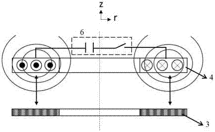
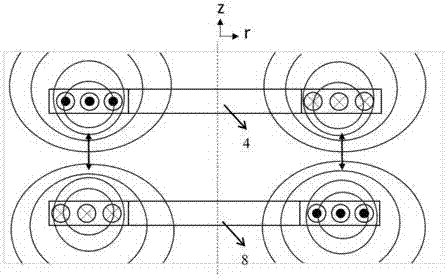
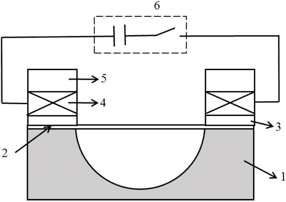
[0030] The invention provides an electromagnetic repulsion force edge-holding device and method based on inertial constraints. Through the energized coil group or the electromagnetic repulsion between the energized coil and the blank-holding copper ring, a convenient and controllable blank-holding force is provided for sheet metal forming, thereby effectively preventing the sheet from wrinkling or cracking.

[0031] In order to achieve the above object, according to one aspect of the present invention, an electromagnetic repulsive force blank holder based on inertial constraints is provided, includ...


PUM


Abstract

The invention discloses an electromagnetic repulsive force edge pressing method and device based on inertial confinement. The method comprises the steps that an edge pressing coil is discharged; the edge pressing coil is arranged on the upper portion of an edge pressing copper ring; the edge pressing copper ring is arranged on the upper portion of the edge of a workpiece; the workpiece is arranged on the upper portion of a female die; the to-be-deformed workpiece is molded through the female die, a pulsed magnet field is generated in the discharging process of the edge pressing coil, induced eddy current correspondingly generated in the edge pressing copper ring and the pulsed magnet field interact, and thus electromagnetic repulsive force is generated between the edge pressing coil and the edge pressing copper ring; and edge pressing force to the edge of the workpiece is provided by the electromagnetic repulsive force between the edge pressing coil and the edge pressing copper ring so that the edge positions of the workpiece can be kept stable in the molding process, meanwhile, workpiece material flowing is controlled, and the workpiece is prevented from being wrinkled and broken in the molding process. Through the electromagnetic repulsive force between two edge pressing coils of between the edge pressing coil and the edge pressing copper ring, the edge pressing force can be flexibly controlled, the device manufacturing cost is reduced, the space size is reduced, and the power source energy of a system can be effectively reduced.

Description

technical field [0001] The invention belongs to the field of metal forming and manufacturing, and more specifically relates to an inertial constraint-based electromagnetic repulsion force blank-holding method and device. Background technique [0002] In the process of sheet metal stamping and forming, problems such as wrinkling, cracking or excessive springback of parts are often faced. In actual production, the method of applying blank holder force is usually used to control the material flow of the sheet metal. Its main function is to apply a certain pressure on the sheet material under the blank holder ring during the stamping forming process, so as to prevent the sheet material from excessively flowing into the mold cavity. Effectively reduce the occurrence of the above-mentioned forming defects. The selection of suitable blank holder force is very critical to the quality control of forming. The traditional blank-holding force is usually applied by a press to apply a c...

Claims


Application Information

Patent Timeline
Patent Type & Authority Applications(China)
IPC IPC(8): B21D26/14
CPCB21D26/14
Inventor 李亮黄玉杰韩小涛曹全梁赖智鹏
Owner HUAZHONG UNIV OF SCI & TECH
Why Eureka
Try Eureka