Stretch forming die with composite structure and manufacturing method of stretch forming die

A composite structure and die-casting technology, which is applied in the direction of manufacturing tools, metal processing equipment, forming tools, etc., can solve the problems that cannot meet the requirements of surface quality, cannot use the precise inspection of the geometric accuracy of the full surface, shape inspection and manufacturing basis, etc. Achieve the effects of eliminating skin bruises, light weight, and reducing total weight

Active Publication Date: 2017-12-01
CHENGDU AIRCRAFT INDUSTRY GROUP
View PDF7 Cites 11 Cited by
  • Summary
  • Abstract
  • Description
  • Claims
  • Application Information

AI Technical Summary

Problems solved by technology

[0010] The mold forming principle and structure of the above-mentioned patents are significantly different: the attached patent belongs to the multi-point forming technology, which discretizes the overall mold and controls the Z-direction coordinates of several scattered and regularly arranged small basic unit bodies (ball cylinders) by computer (height value), forming several three-dimensional "point clouds" in space, so as to form the curved surface shape of the product parts in an "approximate and fitting" way; the mold functions are significantly different: the mold of the multi-point forming technology is a "universal "equipment", which can only be used for part surface forming, and cannot be used for precise inspection of the geometric accuracy of different parts, shape inspection, and other

Method used


Image

  • Stretch forming die with composite structure and manufacturing method of stretch forming die
  • Stretch forming die with composite structure and manufacturing method of stretch forming die
  • Stretch forming die with composite structure and manufacturing method of stretch forming die

Examples


Embodiment 1

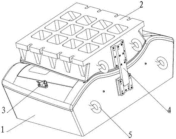
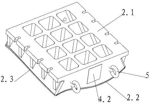
[0063] A drawing die of a composite structure includes an upper die assembly 2 and a lower die assembly 1, the upper die assembly 2 and the lower die assembly 1 are connected through a guide positioning device assembly 4, and the upper die assembly 2 is located at Above the lower mold assembly 1 , the upper surface of the lower mold assembly 1 is provided with a skin component positioning hole 1.5 hole making device assembly, and at least two earring hooks 5 are provided on the side of the lower mold assembly 1 .

Embodiment 2

[0065]A drawing die of a composite structure includes an upper die assembly 2 and a lower die assembly 1, the upper die assembly 2 and the lower die assembly 1 are connected through a guide positioning device assembly 4, and the upper die assembly 2 is located at Above the lower mold assembly 1 , the upper surface of the lower mold assembly 1 is provided with a skin component positioning hole 1.5 hole making device assembly, and at least two earring hooks 5 are provided on the side of the lower mold assembly 1 .

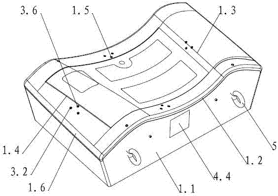
[0066] The lower mold assembly 1 includes a lower mold cast aluminum base 1.1, the upper surface of the lower mold cast aluminum base 1.1 is provided with a wave-shaped lower mold cuttable resin surface layer, and the lower mold can cut the resin mold surface layer The surface inflection point line 1.3, the surface engraved line and the mark and the positioning hole 1.5 of the skin part are respectively arranged on the top, and the edge of the lower mold that can cut ...

Embodiment 3

[0072] A method for manufacturing a drawing die of a composite structure, characterized in that:

[0073] design:

[0074] The first step: Design the lower mold to cut the resin surface layer;

[0075] The specific steps are: extract the outline of the skin part from the theoretical surface of the aircraft or the surface of the digital model of the process 1.4 The profile of the area within 10mm to 30mm along the periphery is used as the basic profile, which is determined by increasing the size of the part blank by 100mm to 200mm on one side Design the transitional surface between the maximum shape and the basic shape; then adjust the shape, determine the best drawing direction, and ensure that the heights of each protrusion are equal; then design the drawing angles and rounding corners on both sides , draw angle 70°-80°, draw fillet greater than R20mm and keep smooth and streamlined; then extract skin part outline 1.4, design part allowance line, positioning lug, first casti...


PUM


Abstract

The invention relates to the field of airplane metal envelope manufacturing, in particular to a stretch forming die with a composite structure and a manufacturing method of the stretch forming die. The stretch forming die comprises an upper die assembly and a lower die assembly, the upper die assembly is connected with the lower die assembly through a guiding positioning device assembly, the upper die assembly is located above the lower die assembly, a hole making device assembly of an envelope part positioning hole is arranged on the upper surface of the lower die assembly, and at least two earring-shaped hooks are arranged on the side face of the lower die assembly. The stretch forming die is provided with a lower die and an upper die , and the upper die and the lower die have the composite structural characteristic, a base body of the stretch forming die adopts a cast aluminum material and is provided with lightening grooves and reinforced ribs so that the total weight of the stretch forming die can be lightened obviously. Dovetail grooves which are distributed in a latticed mode on the molded surface of the cast aluminum base body can firmly hold machinable resin, and effectively prevent a machinable resin layer from cracking and falling down, and the service life of the stretch forming die is prolonged.

Description

technical field [0001] The invention relates to the field of aircraft metal skin manufacturing, in particular to a drawing die of a composite structure and a manufacturing method thereof. Background technique [0002] Due to the needs of the aircraft's aerodynamic shape and functional layout, some skins have a single-curved shape, some have a hyperboloid shape, and some have complex shapes with "S" and partial bulges or depressions. The surface accuracy of skin parts affects the quality of aircraft assembly, and the surface quality defects of metal skin parts such as crushing, scratches, wrinkles, orange peel, etc. affect the fatigue life of aircraft. Therefore, how to produce complex curved skin with high quality and high efficiency is a It is one of the important topics that the aircraft manufacturing main engine factory has been researching and improving. [0003] The drawing die is an important special process equipment for forming aircraft metal skin. Its structure, pr...

Claims


Application Information

Patent Timeline
IPC IPC(8): B21D37/10B21D22/20B21D37/20
CPCB21D22/20B21D37/10B21D37/20
Inventor 张勇兵钟国文何万飞张小波岳维
Owner CHENGDU AIRCRAFT INDUSTRY GROUP
Why Eureka
Try Eureka