Automatic splicing and positioning carrier for frames
A technology for automatic splicing and positioning of carriers, applied in manufacturing tools, welding equipment, auxiliary welding equipment, etc., can solve the problems of reduced welding efficiency, tight production capacity of enterprises, shortage of operators, etc., to avoid fixed position deviation, and the degree of automation The effect of high and low operation difficulty
- Summary
- Abstract
- Description
- Claims
- Application Information
AI Technical Summary
Problems solved by technology
Method used
Image
Examples
Embodiment 1
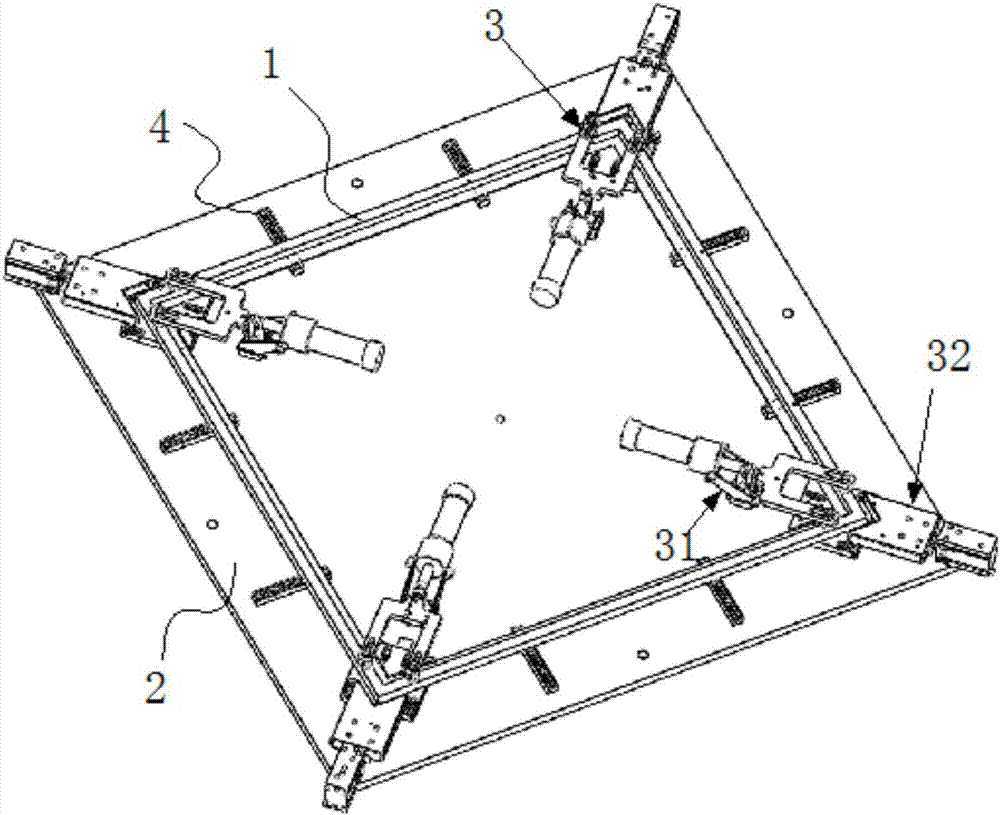
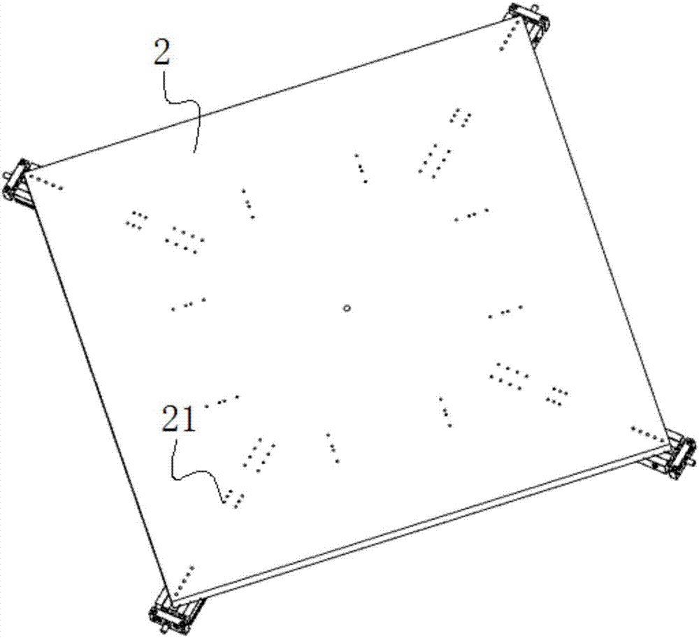
[0034] Embodiment 1: a kind of frame automatic splicing and positioning carrier, such as Figure 1 to Figure 4 As shown, the frame 1 includes a plurality of frame bars that are joined end to end, and the direction close to the frame bars is defined as the front, and includes a carrier plate 2, which is provided with a plurality of groups of splicing positioning mechanisms 3, and each group is spliced and positioned. The mechanisms include a pressing mechanism 31 capable of pressing the adjacent frame bars and a pushing mechanism 32 for pushing the adjacent frame bars to approach, the pressing mechanism is located on the inner side of the frame, and the pushing mechanism is located on the outer side of the frame, And the pressing mechanism and the pushing mechanism of the same group are located on the same straight line;
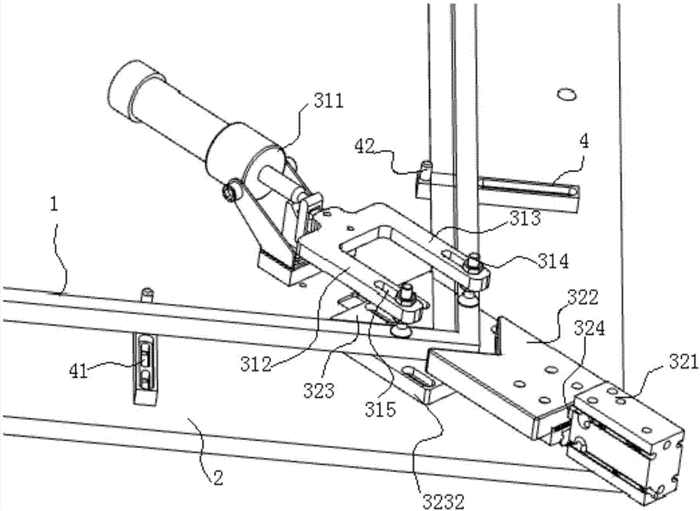
[0035] The pressing mechanism 31 includes a pneumatic elbow clamp 311. The front end of the pneumatic elbow clamp is provided with a set of pressure plates...
Embodiment 2
[0051] Example 2: as Figure 5 to Figure 6 As shown, the structure is the same as that of Embodiment 1, the difference is that the bottom surface of the outer limit block 322 is directly in contact with the carrier plate 2, no guide rail is provided, and the front end of the inner limit block is not provided with a raised base.
[0052] The limiting portion is the front end of the limiting bar, and the frame is located in front of the limiting bar 4 , and the limiting bar is at least one of the inner side and the outer side of the frame 1 .
[0053] The working principle and working process of the present invention are as follows:
[0054] Based on the limit stop bar and the inner limit block, place the frame bar on the carrier board according to the approximate position. After that, start the device. Under the control of the control system, firstly, the push cylinder of the push mechanism pushes the outside through the push rod. The limit block then drives the two adjacent f...
PUM
 Abstract
Description
Claims
Application Information
 - R&D
- Intellectual Property
- Life Sciences
- Materials
- Tech Scout
- Unparalleled Data Quality
- Higher Quality Content
- 60% Fewer Hallucinations
Browse by: Latest US Patents, China's latest patents, Technical Efficacy Thesaurus, Application Domain, Technology Topic, Popular Technical Reports.
© 2025 PatSnap. All rights reserved.Legal|Privacy policy|Modern Slavery Act Transparency Statement|Sitemap|About US| Contact US: help@patsnap.com


