
Suspension structure with transverse composite leaf spring

A technology of composite material plate and horizontal placement, which is applied in the field of vehicle suspension system, can solve the problems of high cost of air springs, potential safety hazards, and small chassis space, and achieve low manufacturing and maintenance costs, simple and convenient installation, and improved The effect of comfort

Pending Publication Date: 2017-12-01
BEIJING JIAPENG MACHINERY CO LTD
View PDF13 Cites 8 Cited by
  • Summary
  • Abstract
  • Description
  • Claims
  • Application Information

AI Technical Summary

Problems solved by technology

[0010] The purpose of the present invention is to provide a suspension structure of horizontally placed composite leaf springs, which overcomes the limitation of the chassis space on the longitudinal installation of the leaf springs in the suspension structure in the prior art and the high cost, short service life and potential safety hazards of the air springs and other issues, making full use of the characteristics of light specific gravity and good energy absorption of composite leaf springs to achieve the purpose of the suspension structure occupying less space on the chassis and having a long service life, effectively reducing costs and improving safety

Method used


Image

  • Suspension structure with transverse composite leaf spring
  • Suspension structure with transverse composite leaf spring
  • Suspension structure with transverse composite leaf spring

Examples


Embodiment Construction

[0046] In order to have a clearer understanding of the technical features, purposes and effects of the present invention, the specific implementation manners of the present invention will now be described with reference to the accompanying drawings.

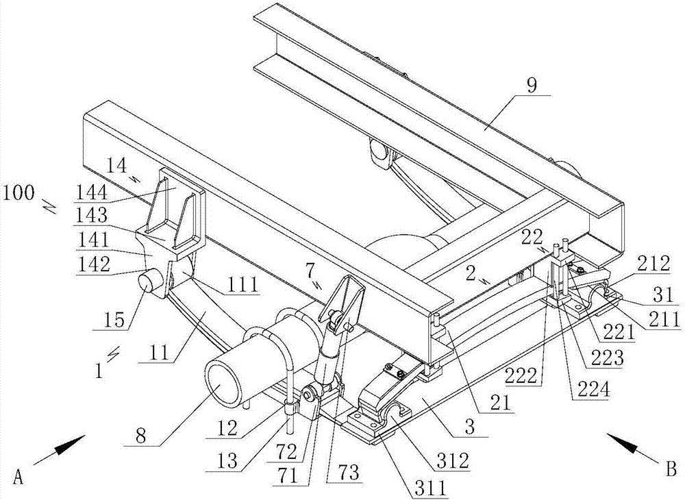
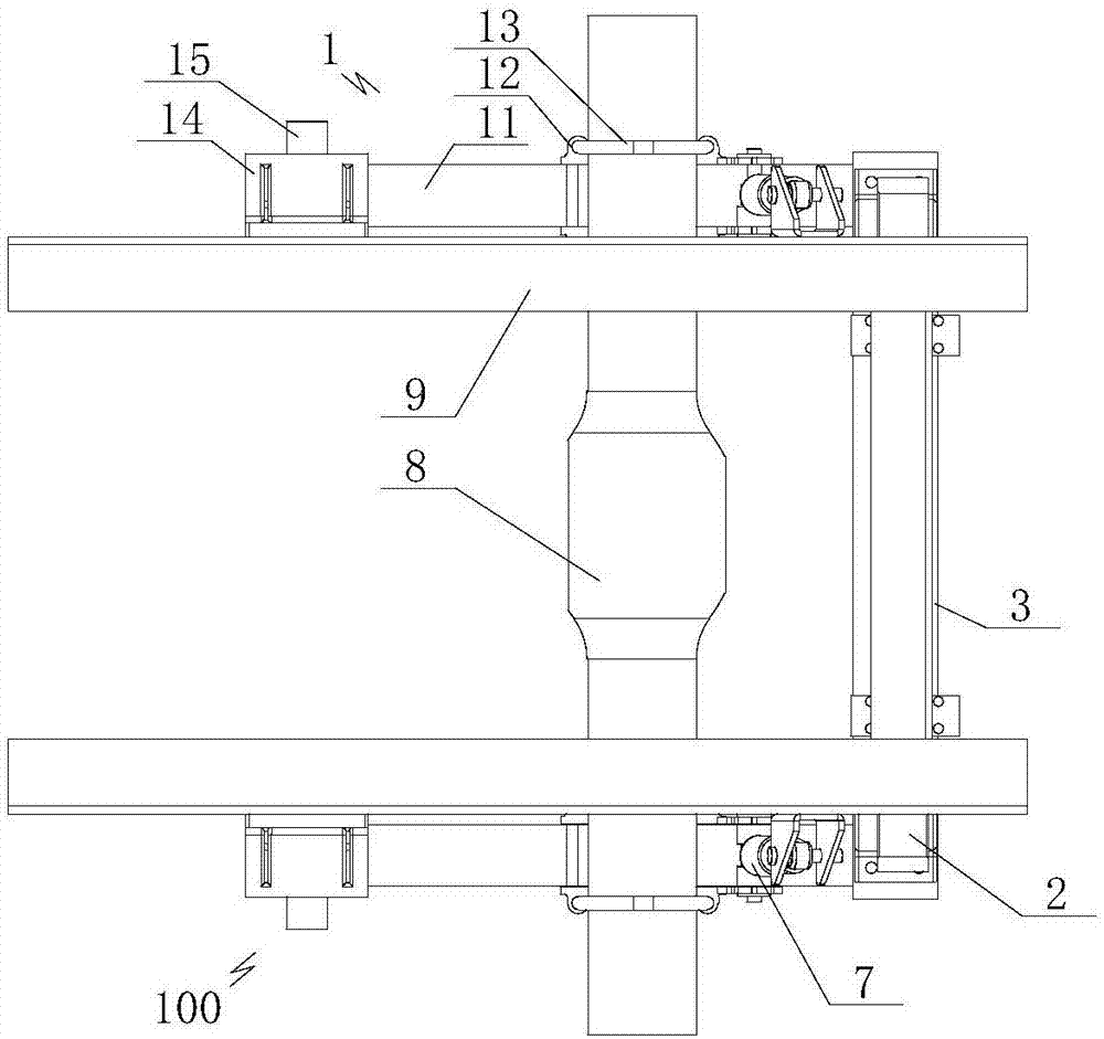
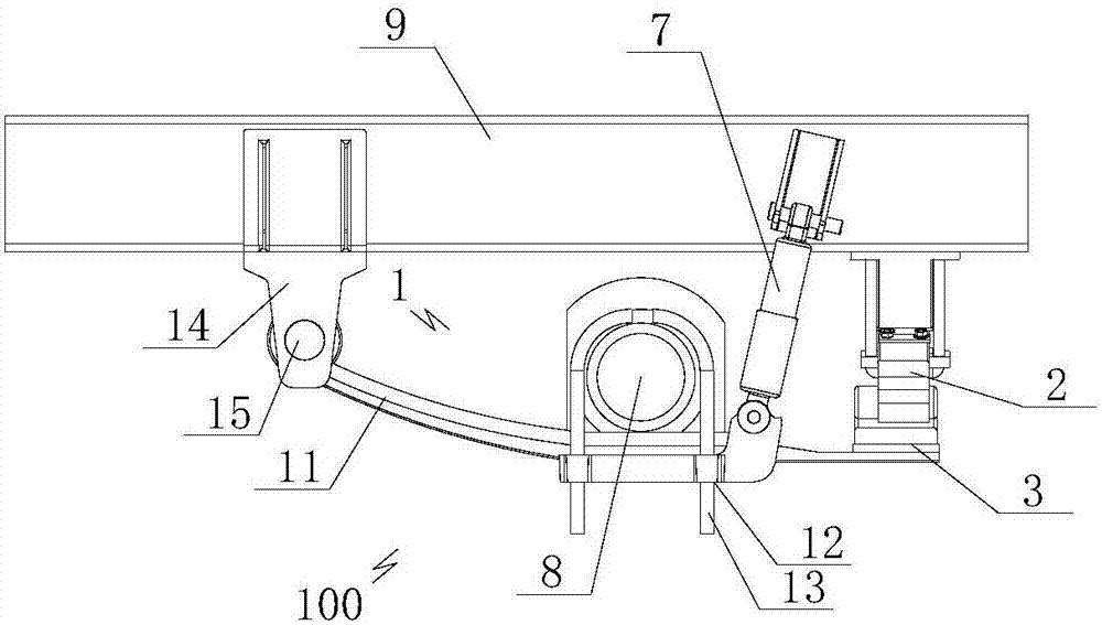
[0047] Such as Figure 1 to Figure 4 As shown, the present invention provides a horizontal composite material leaf spring suspension structure 100, which includes a main frame 9 (the prior art, which plays a role in carrying the weight of the whole vehicle), and the two sides are respectively provided with axle connection structures 1. A vehicle axle connecting structure 1 is used to connect vehicle axle 8 (in the prior art, through the effect of the wheels installed on its end and the ground, the whole vehicle is supported and driven) and the main frame 9, and the two vehicles The length direction of the bridge connection structure 1 and the longitudinal direction of the main frame 9 (in the field of automobile engineering, the ...


PUM


Abstract

The invention relates to a suspension structure with a transverse composite leaf spring. The suspension structure comprises vehicle axle connection structures respectively arranged at two sides below a main vehicle frame, wherein the two vehicle axle connection structures are used for connecting a vehicle axle with the main vehicle frame; the longitudinal direction of the two vehicle axle connection structures is arranged in parallel with the longitudinal direction of the main vehicle frame; shock absorption structures are arranged between the two vehicle axle connection structures and the main vehicle frame; and a transverse composite leaf spring structure capable of expanding and contracting in the transverse direction of the main vehicle frame and being connected with the main vehicle frame is arranged between the opposite ends of the two vehicle axle connection structures. The suspension structure with the transverse composite leaf spring overcomes the problem that the longitudinal installation of the leaf spring in the suspension structure is limited by the space of a chassis in the prior art and the problems of high cost, short service life, hidden dangers and the like of air springs in the prior art, and has the advantages of making full use of light weight, good energy absorption capacity and other characteristics of the composite leaf spring, occupying little space on the chassis, increasing service life, effectively reducing the cost and improving the safety.

Description

technical field [0001] The invention relates to the technical field of vehicle suspension systems, in particular to a suspension structure of a transverse composite material leaf spring. Background technique [0002] Automobile suspension system (also known as automobile suspension system) is a general term for all force transmission connection devices between the frame and axle or wheels of the automobile. Its function is to transmit the force and moment acting between the frame and the wheels, and Buffer the impact force transmitted from the uneven road to the frame or body, and attenuate the resulting vibration to ensure the smooth running of the car. The automobile suspension system mainly includes three parts, which are elastic elements (elements that bear and transmit vertical loads in the suspension system and have the ability to ease and suppress the impact caused by the road surface), shock absorbers and guide mechanisms. [0003] At present, elastic components mai...

Claims


Application Information

Patent Timeline
IPC IPC(8): B60G11/08B60G11/10
CPCB60G11/08B60G11/10B60G2202/114B60G2200/32Y02T10/86
Inventor 刘雪品陈茂远伊江
Owner BEIJING JIAPENG MACHINERY CO LTD
Learn More