Method for measuring free hemoglobin by double-optical-path multiposition intra-frequency-domain fluorescence light intensity
A technology of hemoglobin and fluorescent light, which is applied in the field of measuring free hemoglobin with fluorescent light intensity, can solve the problems of non-linear light intensity and inability to completely eliminate fluorescent background noise, achieve suppression and blood scattering, solve non-destructive testing problems, and have strong measurement pertinence Effect
- Summary
- Abstract
- Description
- Claims
- Application Information
AI Technical Summary
Problems solved by technology
Method used
Image
Examples
Embodiment 1
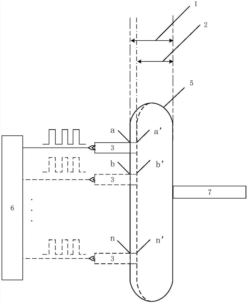
[0059] The embodiment of the present invention provides a method for measuring free hemoglobin with fluorescence light intensity in the frequency domain with dual optical paths and multiple positions, and the devices used are such as figure 2 As shown, it includes: a fluorescent excitation light source 3 , a blood bag 5 , a displacement platform 6 and a light intensity receiving device 7 .
[0060] Wherein, ensure that the light output port of the fluorescence excitation light source 3 and the incident slit of the light intensity receiving device 7 are close to the blood bag 5, drive the fluorescence excitation light source 3 with a square wave signal to make it emit a square wave light signal, and the fluorescence excitation light source 3 is at position a Under the two optical paths at position a (corresponding to the first optical path 1) and position a' (corresponding to the second optical path 2), the blood sample in the blood bag 5 is excited, and the fluorescence is rec...
Embodiment 2
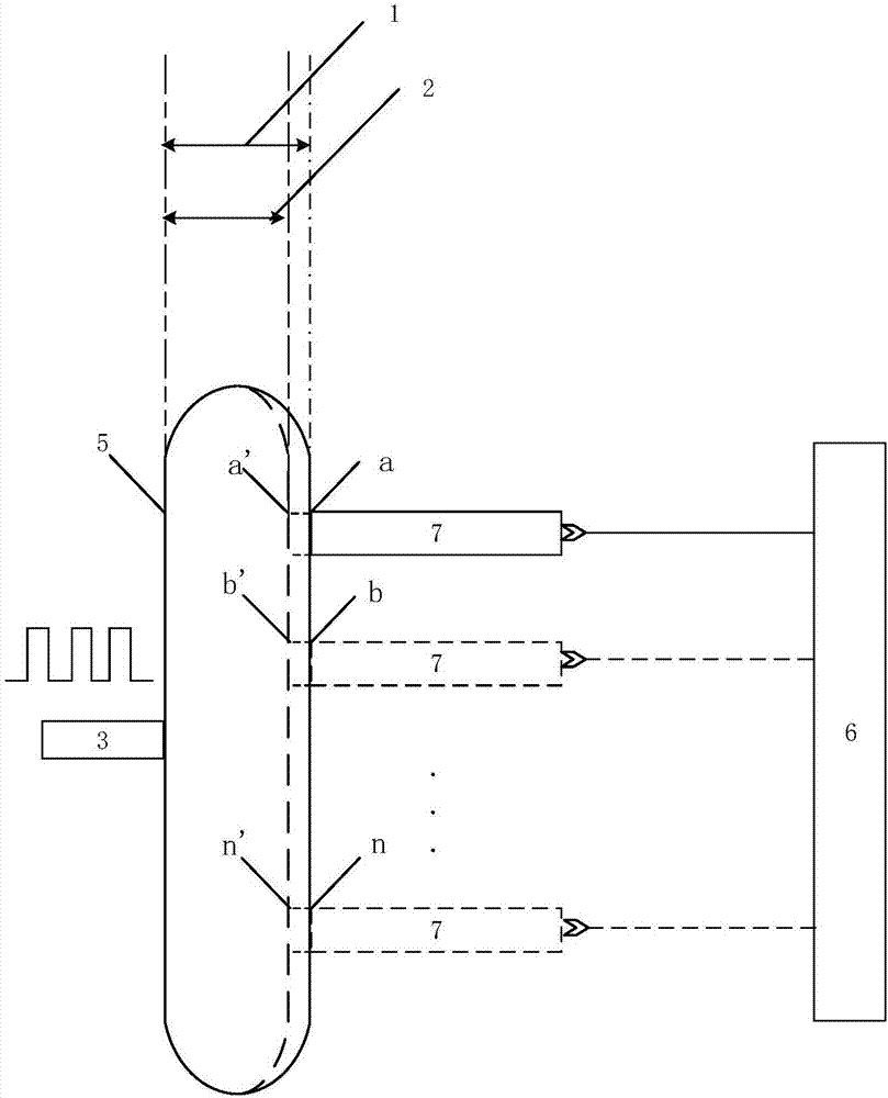
[0067] The difference between the embodiment of the present invention and the embodiment 1 is only that the fluorescence excitation light source 3 and the movement mode of the light intensity receiving device 7 are different, see the following description for details:
[0068] see image 3 , ensure that the light exit port of the fluorescence excitation light source 3 and the incident slit of the light intensity receiving device 7 are close to the blood bag 5, drive the fluorescence excitation light source 1 with a square wave signal to make it emit a square wave light signal, and the fluorescence excitation light source 3 matches the blood bag 5 The blood sample inside is excited, and the light intensity receiving device 7 receives the fluorescence light intensity at the position a under the double optical path: position a and position a'. Control the light intensity receiving device 7 to move to position b through the displacement platform 6, and receive the fluorescent ligh...
Embodiment 3
[0073] During specific implementation, due to the limitation of the space structure, it may occur that the fluorescence excitation light source 3 and the light intensity receiving device 7 cannot be close to the blood bag 5. An optical fiber is used as an incident optical fiber 4 and an outgoing optical fiber 8 .
[0074] see Figure 4 The fluorescence excitation light source 1 is driven by a square wave signal to emit a square wave light signal, the fluorescence excitation light source 3 excites the blood sample in the blood bag 5 through the incident optical fiber 4, and the fluorescence light intensity is received by the light intensity receiving device 7 through the exit optical fiber 8 , the incident optical fiber 4 and the outgoing optical fiber 8 are respectively close to the blood bag 5, the incident optical fiber 4 is at position a, and the fluorescence excitation light source 3 passes through the incident optical fiber 4 at this position. Excitation is carried out, ...
PUM
 Abstract
Description
Claims
Application Information
 - R&D
- Intellectual Property
- Life Sciences
- Materials
- Tech Scout
- Unparalleled Data Quality
- Higher Quality Content
- 60% Fewer Hallucinations
Browse by: Latest US Patents, China's latest patents, Technical Efficacy Thesaurus, Application Domain, Technology Topic, Popular Technical Reports.
© 2025 PatSnap. All rights reserved.Legal|Privacy policy|Modern Slavery Act Transparency Statement|Sitemap|About US| Contact US: help@patsnap.com


