Method of additive manufacturing using photoregulated radical polymerization

A methyl and alkyl technology, applied in the field of additive manufacturing, can solve problems such as weak adhesion and low hygroscopicity

Active Publication Date: 2017-12-01
DOW GLOBAL TECH LLC
View PDF3 Cites 0 Cited by
  • Summary
  • Abstract
  • Description
  • Claims
  • Application Information

AI Technical Summary

Problems solved by technology

Additionally, weak cohesion, hygroscopicity and low powder recyclability have been mentioned as disadvantages of SLS using known polymer raw materials
Attempts have been made to add additives, such as fillers, to address these disadvantages, but this has met with only limited success due to the high viscosity of the polymer - high viscosity prevents uniform loading of additives to the polymer

Method used


Image

  • Method of additive manufacturing using photoregulated radical polymerization
  • Method of additive manufacturing using photoregulated radical polymerization
  • Method of additive manufacturing using photoregulated radical polymerization

Examples


Embodiment 2

[0043] Embodiment 2 encompasses the photoredox catalyst of embodiment 1 wherein each Z is R 13 ,-B-(A) 2 ,-B-(R 13 ) 2 、-B(A)(R 13 ), -N-(A) 2 , -N-(R 13 ) 2 、-N(A)(R 13 ), -Si-(R 13 ) 3 , -Si(A) 3 , -Si(A) 2 (R 13 ) or -Si(A)(R 13 ) 2 . Specifically, in Example 2, each Z is R 13 ,-B-(R 13 ) 2 , -N-(R 13 ) 2 or -Si-(R 13 ) 3 . Specifically, in Example 2, each Z is R 13 ,-B-(A) 2 、-B(A)(R 13 ), -N-(A) 2 、-N(A)(R 13 ), -Si(A) 3 , -Si(A) 2 (R 13 ) or -Si(A)(R 13 ) 2 . Specifically, in Example 2, each Z is R 13 ,-B-(A) 2 ,-B-(R 13 ) 2 ,-N-(A) 2 , -N-(R 13 ) 2 , -Si-(R 13 ) 3 or -Si(A)(R 13 ) 2 . Embodiment 3 covers the photoredox catalyst of embodiment 1 wherein each Z is R 13 ,-B-(A) 2 ,-B-(R 13 ) 2 、-B(A)(R 13 ), -N-(A) 2 , -N-(R 13 ) 2 or -N(A)(R 13 ). Specifically, in Example 3, each Z is R 13 ,-B-(A) 2 ,-B-(R 13 ) 2 ,-N-(A) 2 or -N-(R 13 ) 2 . Embodiment 4 covers the photoredox catalyst of embodiment 1, wherein eac...

Embodiment 8

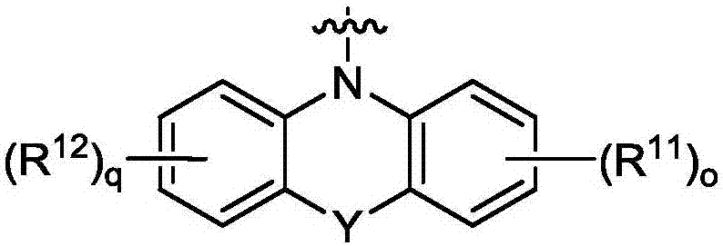
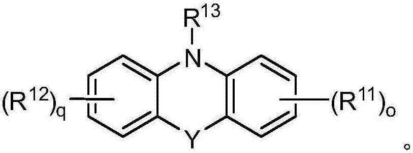
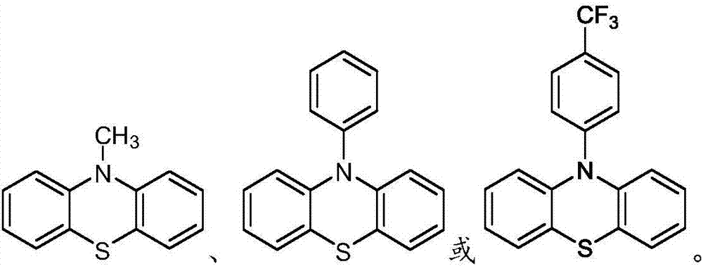
[0046] Specific compounds of Example 8 include those of Example 9, i.e., wherein Y is O, S, NR 14 or C(R 14 ) 2 photoredox catalyst. In embodiment 10, the disclosure provides the photoredox catalyst of embodiment 8 or 9, wherein Y is O, S or NR 14 . In embodiment 11, the present disclosure provides the photoredox catalyst of embodiment 8 or 9, wherein Y is O or S. In embodiment 12, the present disclosure provides the photoredox catalyst of embodiment 8 or 9, wherein Y is S. In embodiment 13, the disclosure provides the photoredox catalyst of embodiment 8 or 9, wherein Y is C(R 14 ) 2 . Embodiment 14 covers the photoredox catalyst of embodiment 8, wherein Y is absent.

Embodiment 15

[0047] Embodiment 15 encompasses the photoredox catalyst of any one of embodiments 8 to 14, wherein o and q are independently zero.

[0048] In embodiment 16, the disclosure provides the photoredox catalyst of any one of embodiments 8-14, wherein at least one of o and q is 1. Embodiment 17 covers the photoredox catalyst of embodiment 16, wherein R 11 and R 12 independently selected from the group consisting of hydrogen, halogen, cyano, hydroxyl, amino, mono(C 1 -C 20 ) Alkylamino or two (C 1 -C 20 ) Alkylamino, C 1 -C 6 Alkyl and C 1 -C 6 alkoxy. Specifically, in Example 17, R 11 and R 12 independently selected from the group consisting of hydrogen, halogen, hydroxyl, amino, mono(C 1 -C 20 ) Alkylamino or two (C 1 -C 20 ) Alkylamino, C 1 -C 6 Alkyl and C 1 -C 6 alkoxy.

[0049] Specific embodiments based on Examples 8 to 17 include those of Example 18, i.e., wherein R 13 for C 1 -C 20 Alkyl, -C(O)C 1 -C 20 Alkyl, C 3 -C 7 Cycloalkyl, aryl, aryl (C 1...


PUM


Abstract

A method of fabricating a three-dimensional object, the method comprising: combining at least one of a meth(acrylate), a (meth)acrylamide, a (meth)acrylonitrile, a styrene, an acrylonitrile, a vinyl acetate, a vinylcarbazole, a vinylpyridine, a vinyl ether, a vinyl chloride monomers, a polyfunctional monomer, and a polyfunctional prepolymer with an organic photoredox catalyst to provide a reaction mixture; depositing the reaction mixture; polymerizing the monomers by irradiating the reaction mixture with a light source; and repeating the depositing step until the three-dimensional object is formed.

Description

Background technique [0001] The present disclosure relates to additive manufacturing and in particular to methods of making objects via additive manufacturing using photoredox catalysts to achieve metal-free light-tuned free radical polymerization. [0002] Additive manufacturing is generally a method in which three-dimensional (3D) objects are made based on a computer model of the object. These methods are used in a variety of fields, such as design-related fields for visualization, demonstration, and mechanical prototyping purposes. [0003] 3D printing is an example of additive manufacturing. 3D printing methods include Fused Deposition Modeling (FDM) and Selective Laser Sintering (SLS). Materials used in 3D printing are typically polymers; common examples include acrylonitrile butadiene styrene (ABS), polylactic acid (PLA), polyamide, polyether ether ketone (PEEK), and thermoplastic polyurethane ( TPU). [0004] Many factors are considered when choosing a 3D printing m...

Claims


Application Information

Patent Timeline
Patent Type & Authority Applications(China)
IPC IPC(8): B29C67/00G03F7/00
CPCG03F7/0037B33Y70/00G03F7/027G03F7/029G03F7/031B29C64/135
Inventor P·克拉克J·W·克雷默A·J·帕其克
Owner DOW GLOBAL TECH LLC
Why Eureka
Try Eureka