Additive Manufacturing Method Using Light-Tuned Radical Polymerization
A methyl and alkyl technology, applied in the field of additive manufacturing, can solve problems such as low hygroscopicity and weak adhesion
- Summary
- Abstract
- Description
- Claims
- Application Information
AI Technical Summary
Problems solved by technology
Method used
Image
Examples
Embodiment 2
[0043] Embodiment 2 encompasses the photoredox catalyst of embodiment 1 wherein each Z is R 13 ,-B-(A) 2 ,-B-(R 13 ) 2 、-B(A)(R 13 ), -N-(A) 2 , -N-(R 13 ) 2 、-N(A)(R 13 ), -Si-(R 13 ) 3 , -Si(A) 3 , -Si(A) 2 (R 13 ) or -Si(A)(R 13 ) 2 . Specifically, in Example 2, each Z is R 13 ,-B-(R 13 ) 2 , -N-(R 13 ) 2 or -Si-(R 13 ) 3 . Specifically, in Example 2, each Z is R 13 ,-B-(A) 2 、-B(A)(R 13 ), -N-(A) 2 、-N(A)(R 13 ), -Si(A) 3 , -Si(A) 2 (R 13 ) or -Si(A)(R 13 ) 2 . Specifically, in Example 2, each Z is R 13 ,-B-(A) 2 ,-B-(R 13 ) 2 ,-N-(A) 2 , -N-(R 13 ) 2 , -Si-(R 13 ) 3 or -Si(A)(R 13 ) 2 . Embodiment 3 covers the photoredox catalyst of embodiment 1 wherein each Z is R 13 ,-B-(A) 2 ,-B-(R 13 ) 2 、-B(A)(R 13 ), -N-(A) 2 , -N-(R 13 ) 2 or -N(A)(R 13 ). Specifically, in Example 3, each Z is R 13 ,-B-(A) 2 ,-B-(R 13 ) 2 ,-N-(A) 2 or -N-(R 13 ) 2 . Embodiment 4 covers the photoredox catalyst of embodiment 1, wherein eac...
Embodiment 8
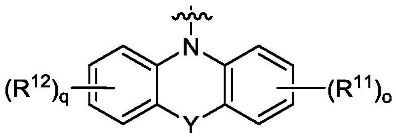
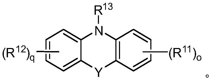
[0046] Specific compounds of Example 8 include those of Example 9, i.e., wherein Y is O, S, NR 14 or C(R 14 ) 2 photoredox catalyst. In embodiment 10, the disclosure provides the photoredox catalyst of embodiment 8 or 9, wherein Y is O, S or NR 14 . In embodiment 11, the present disclosure provides the photoredox catalyst of embodiment 8 or 9, wherein Y is O or S. In embodiment 12, the present disclosure provides the photoredox catalyst of embodiment 8 or 9, wherein Y is S. In embodiment 13, the disclosure provides the photoredox catalyst of embodiment 8 or 9, wherein Y is C(R 14 ) 2 . Embodiment 14 covers the photoredox catalyst of embodiment 8, wherein Y is absent.
Embodiment 15
[0047] Embodiment 15 encompasses the photoredox catalyst of any one of embodiments 8 to 14, wherein o and q are independently zero.
[0048] In embodiment 16, the disclosure provides the photoredox catalyst of any one of embodiments 8-14, wherein at least one of o and q is 1. Embodiment 17 covers the photoredox catalyst of embodiment 16, wherein R 11 and R 12 independently selected from the group consisting of hydrogen, halogen, cyano, hydroxyl, amino, mono(C 1 -C 20 ) Alkylamino or two (C 1 -C 20 ) Alkylamino, C 1 -C 6 Alkyl and C 1 -C 6 alkoxy. Specifically, in Example 17, R 11 and R 12 independently selected from the group consisting of hydrogen, halogen, hydroxyl, amino, mono(C 1 -C 20 ) Alkylamino or two (C 1 -C 20 ) Alkylamino, C 1 -C 6 Alkyl and C 1 -C 6 alkoxy.
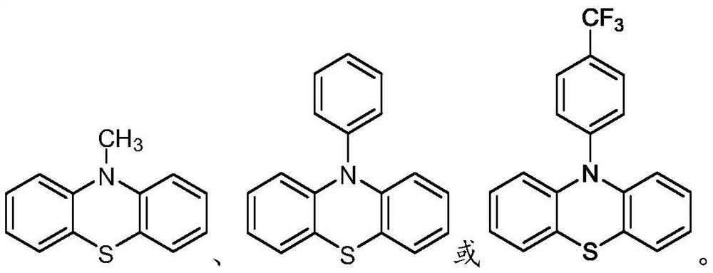
[0049] Specific embodiments based on Examples 8 to 17 include those of Example 18, i.e., wherein R 13 for C 1 -C 20 Alkyl, -C(O)C 1 -C 20 Alkyl, C 3 -C 7 Cycloalkyl, aryl, aryl (C 1...
PUM
 Abstract
Description
Claims
Application Information
 - R&D
- Intellectual Property
- Life Sciences
- Materials
- Tech Scout
- Unparalleled Data Quality
- Higher Quality Content
- 60% Fewer Hallucinations
Browse by: Latest US Patents, China's latest patents, Technical Efficacy Thesaurus, Application Domain, Technology Topic, Popular Technical Reports.
© 2025 PatSnap. All rights reserved.Legal|Privacy policy|Modern Slavery Act Transparency Statement|Sitemap|About US| Contact US: help@patsnap.com


