Electric machinery end cover capable of preventing shaft current

A motor end cover and shaft current technology, which is applied to transformer/inductor parts, circuits, electrical components, etc., can solve the problems of bearing grease loss and aging, lack of motor end cover anti-axis current, and electrochemical corrosion of motor bearings. , to achieve improved safety performance, good market prospects, and good additive performance

Inactive Publication Date: 2017-12-08
HARBIN UNIV OF SCI & TECH
View PDF7 Cites 2 Cited by
  • Summary
  • Abstract
  • Description
  • Claims
  • Application Information

AI Technical Summary

Problems solved by technology

[0003] The existing motor end cover lacks the design of anti-shaft current. Due to the possible machining errors in the production of stator punching, the magnetic circuit is asymmetrical, resulting in shaft voltage at both ends of the rotating shaft. After the motor has been running for a long time, the bearing lubrication Grease will gradually lose and age, resulting in the easy formation of shaft current between the motor end cover, bearing and shaft, causing electrochemical corrosion of the motor bearing, seriously affecting the service life of the bearing and the motor, and the shaft current will discharge from the shaft through the bearing, After long-term operation, the bearing rolls to damage, there are potential safety hazards in the operation of the motor, and the operating reliability of the motor is reduced

Method used


Image

  • Electric machinery end cover capable of preventing shaft current
  • Electric machinery end cover capable of preventing shaft current

Examples


Embodiment Construction

[0018] The present invention will be described in detail below in conjunction with the accompanying drawings.

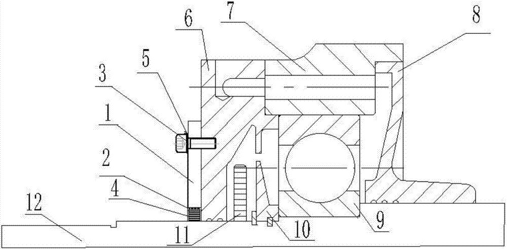
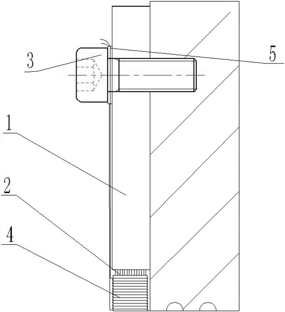
[0019] to combine Figure 1 to Figure 2 As shown, a motor end cover for preventing axial current disclosed in this embodiment includes a motor front end cover 7, a motor front bearing outer cover 6, a motor front bearing inner cover 8, a motor bearing 9, and a motor shaft 12; the motor shaft 12 is fixedly provided with motor bearing 9 and bearing pressure sleeve 10, and described motor rotating shaft 12, described motor bearing 9 and described bearing pressure sleeve 10 are arranged in motor front end cover 7, and the outer surface of described motor front end cover 6 and The inner surface is respectively provided with a motor front bearing cover 6 and a machine front bearing inner cover 5; the conductive device is fixedly installed on the front end surface of the motor front bearing cover 6 by bolts 3, and the motor front bearing cover 6 is connected with the motor ...


PUM


Abstract

The invention discloses an electric machinery end cover capable of preventing shaft current. The electric machinery end cover herein includes an electric machinery front end cover. An electric machinery rotation shaft is fixedly provided with an electric machinery bearing and a bearing pressing sleeve. The electric machinery rotation shaft, the electric machinery bearing and the bearing pressing sleeve are disposed inside the electric machinery front end cover. The external surface and the internal surface of the electric machinery bearing are separately provided with an electric machinery front bearing external cover and an electric machinery front bearing internal cover. A conductive apparatus is in fixed installation to the electric machinery front bearing external cover through a bolt. The electric machinery front bearing external cover and the bearing are provided with a cavity therebetween. The cavity is provided with a thrower ring therein, and the thrower ring and the electric machinery rotation shaft are in fixed connection. According to the invention, the electric machinery end cover is provided with a shaft current prevention apparatus thereon, such that current goes through the electric machinery end cover, the electric machinery front bearing external cover, a conducting ring, a conductive fiber, and the rotation shaft rather than go through the original electric machinery front end cover, the bearing and the rotation shaft, so that the electric machinery end cover prevents current from going through the electric machinery bearing, prolongs service life of the bearing, and provides better protection to the electric machinery.

Description

Technical field: [0001] The invention relates to the technical field of motors, in particular to a motor end cover for preventing shaft current. Background technique: [0002] Motor end cover: It is the cover of the motor casing. Generally, it is divided into a front cover and a rear cover, which are used to fix and support the motor shaft; the material of the motor end cover is generally metal, including cast aluminum, cast iron, alloy steel, etc. Generally, different materials are selected according to different motor types; for example, most automotive motors are made of cast aluminum and cast iron, and large motors use die-casting technology; [0003] The existing motor end cover lacks the design to prevent shaft current. Due to the possible processing errors in the production of stator punching, the magnetic circuit is asymmetrical, resulting in shaft voltage at both ends of the shaft. After the motor has been running for a long time, the bearings are lubricated Greas...

Claims


Application Information

Patent Timeline
Patent Type & Authority Applications(China)
IPC IPC(8): H02K5/04H02K5/16H01F27/30
CPCH02K5/04H01F27/306H02K5/16
Inventor 戈宝军朱一枫韩继超罗前通魏瑶吕飞黄帅
Owner HARBIN UNIV OF SCI & TECH
Why Eureka
Try Eureka