Articulation method of fixed articulation of low-floor vehicle and articulation device of fixed articulation
A technology of low-floor vehicles and fixed hinges, which is applied in the direction of trucks, transport passenger cars, vehicle parts, etc., can solve the problems of large installation space, complex structure of fixed hinges, and difficult maintenance, and achieve stable motion, good motion deflection ability, and maintenance Convenient and reliable effect
- Summary
- Abstract
- Description
- Claims
- Application Information
AI Technical Summary
Problems solved by technology
Method used
Image
Examples
Embodiment 1
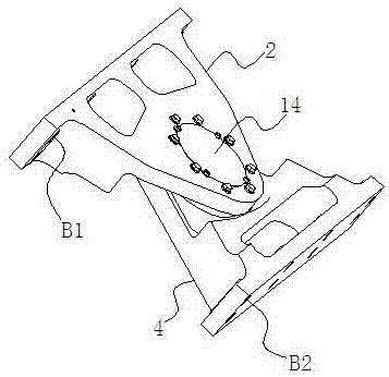
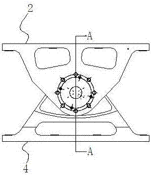
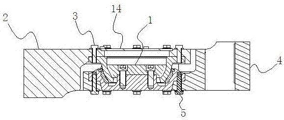
[0034] Embodiment 1: as Figure 1 to Figure 3 As shown, a low-floor vehicle fixed hinge hinge method, it is first assembled into a whole metal joint bearing 1 in the low-floor vehicle fixed hinge, and then the integrated metal joint bearing and an upper fixed support of a car body 2 is connected by connecting piece 1 3 and the integral metal joint bearing 1 is connected with the lower fixed support 4 of another vehicle body by connecting piece 2 5, thereby connecting two adjacent vehicle bodies. The metal joint bearings in the fixed hinges of existing low-floor vehicles usually have different structures according to different loads and requirements for the radius of the curve. Since they are mainly used in urban transportation, the radius of the curve is required to be as small as possible. At the same time, urban Design according to the size of passenger flow. As the core component of the fixed joint system, it has high requirements in terms of load capacity and motion trans...
Embodiment 2
[0043] Embodiment 2: as Figure 8 As shown, compared with Embodiment 1, the difference is that a wear-resistant bushing 2 16 is also arranged between the inner rolling ball 8 and the outer rolling ball sleeve 7, and the outer rolling ball sleeve 7 and the wear-resistant bushing 2 16 All through spherical contact between and between the inner rolling ball 8 and the wear-resistant bushing two 16. Wear-resistant bushing 2 16 adopts copper-based PTFE inlay, copper-based graphite inlay, engineering plastics or nylon, the selection of the material of wear-resistant bush 2 16 and the material of wear-resistant bush 1 9 described in Example 1 The selection of is the same and will not be repeated here. Through the setting of wear-resistant bushing 1 and wear-resistant bushing 2, the metal joint bearing in this embodiment has excellent anti-friction lubrication and load-carrying capacity, extremely low friction coefficient, good self-lubricating effect and high Excellent bearing capac...
Embodiment 3
[0045] Embodiment 3: as Figure 9 As shown, compared with Example 2, the difference is that by adjusting the thickness of the wear-resistant bushing 2 16, the gap between the inner rolling ball 8 and the outer rolling ball sleeve 7 is changed, thereby changing the performance of the metal joint bearing. The fixed hinge of the entire low-floor vehicle can be adapted to different working conditions and has wider versatility. This is because by adjusting the thickness of the wear-resistant bushing 2, the structural size of the contact surface of the inner rolling ball or the outer rolling ball sleeve can be changed, thereby changing the structural strength of the product, thereby adapting to the load requirements under different working conditions; in addition, by adjusting The thickness of the wear-resistant bushing 2 can also adapt to the friction requirements under different working conditions.
[0046] In this embodiment, a gap adjusting gasket 18 is provided between the inn...
PUM
 Abstract
Description
Claims
Application Information
 - R&D
- Intellectual Property
- Life Sciences
- Materials
- Tech Scout
- Unparalleled Data Quality
- Higher Quality Content
- 60% Fewer Hallucinations
Browse by: Latest US Patents, China's latest patents, Technical Efficacy Thesaurus, Application Domain, Technology Topic, Popular Technical Reports.
© 2025 PatSnap. All rights reserved.Legal|Privacy policy|Modern Slavery Act Transparency Statement|Sitemap|About US| Contact US: help@patsnap.com


