
Metal component quick forming method

A metal component and rapid technology, applied in the field of metallurgy, can solve problems such as low efficiency and low quality, and achieve the effects of increased production efficiency, low requirements for production raw materials and production organization, and flexible production organization

Active Publication Date: 2017-12-12
MAANSHAN SHANGYUAN METALLURGICAL TECH CO LTD
View PDF4 Cites 0 Cited by
  • Summary
  • Abstract
  • Description
  • Claims
  • Application Information

AI Technical Summary

Problems solved by technology

[0007] The purpose of the present invention is to overcome the disadvantages of low efficiency and low quality of the existing rapid prototyping technology when forming large-scale structural parts, and to provide a rapid prototyping method for metal components, which combines rapid prototyping technology and special metallurgical technology The combination of advantages can significantly improve the production efficiency and product quality of rapid prototyping of large-scale metal components

Method used


Image

  • Metal component quick forming method
  • Metal component quick forming method

Examples


Embodiment 1

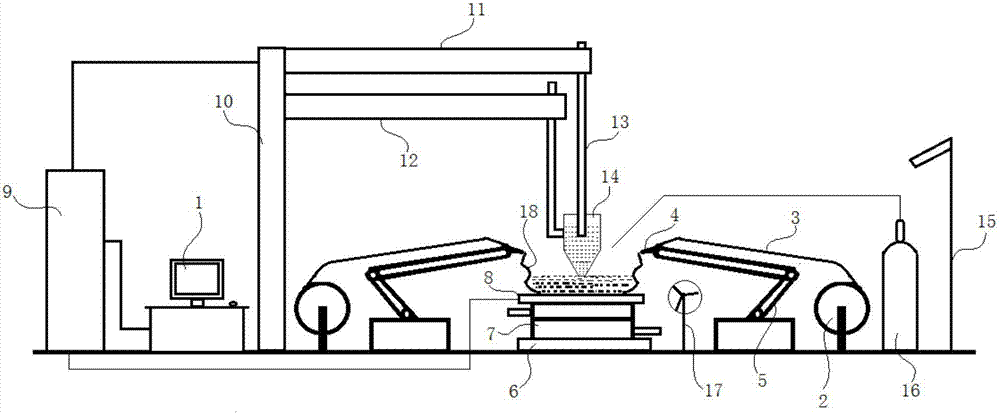
[0040] combine figure 1, the rapid prototyping device for metal components in this embodiment includes a power supply 1, a consumable electrode 13, a refiner 14, and an additive manufacturing mechanism connected to a computer 9; the additive manufacturing mechanism is used to 3D print out The metal component shell 18, the printed metal component shell 18 is filled with refining slag, wherein the bearing plate 8 is a metal plate, the bearing plate 8 is placed on the cooling mechanism 7, the cooling mechanism 7 is a cooling device for a water-cooled box, and the cooling mechanism 7 is set On the insulating plate 6; the refiner 14 is composed of upper and lower sections, the upper section is a hollow cylinder, the lower section is an inverted hollow round table, the upper section and the lower section are seamlessly welded together, the lower end of the refiner 14 faces the inside of the metal component shell 18, The refiner 14 is filled with refining slag; the consumable electro...


PUM


Abstract

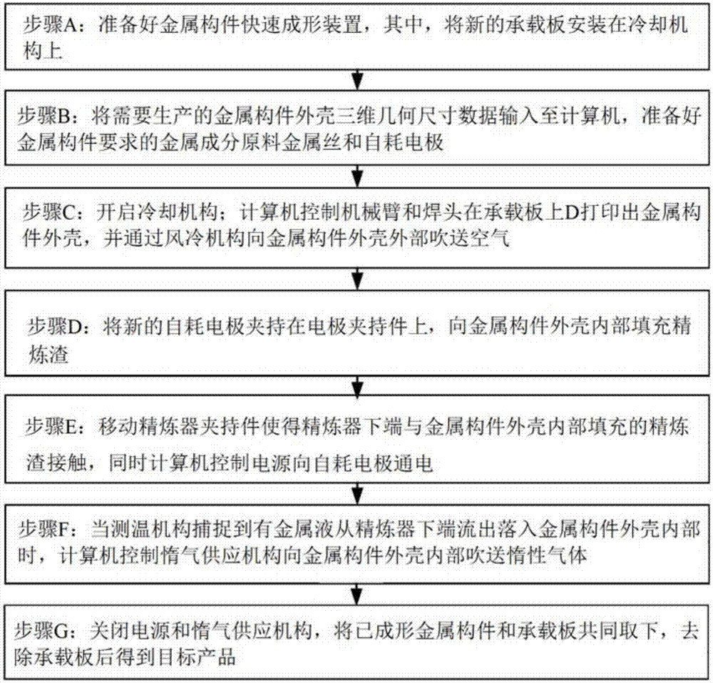
The invention discloses a metal component quick forming method, and belongs to the technical field of metallurgy. The metal component quick forming method comprises the following steps: (A) a metal component quick forming device is prepared; (B) three-dimensional geometric size data of a metal component shell is input in a computer; (C) a mechanical arm and a welding head are used for 3D printing of the metal component shell on a bearing plate; (D) a new consumable electrode is clamped on an electrode clamping piece; and refining slag is filled in the metal component shell; (E) the consumable electrode is electrified; (F) inert gas is blown; and (G) a power supply and an inertia gas supply mechanism are closed. In order to overcome the defects of lower efficiency and lower quality in formation of large-size structural parts by a traditional quick forming technology, the invention provides the metal component quick forming method; and the advantages of the quick forming process and the special metallurgy process are combined to prominently improve the production efficiency of quick forming of large-size metal components and the product quality.

Description

technical field [0001] The invention belongs to the technical field of metallurgy, and more specifically relates to a rapid prototyping method for metal components, which is suitable for component manufacturing of iron and steel materials and other metal materials. Background technique [0002] At present, the technologies that can directly obtain irregular parts are mainly casting technology and rapid prototyping technology. Casting technology has been developed for a long time, and molten steel can be directly formed, but the production efficiency is too low, so it is suitable for the manufacture of complex parts. Rapid prototyping technology is a new processing technology that appeared in the late 1980s. It integrates the latest achievements in the fields of modern numerical control technology, CAD / CAM technology and material science, and can automatically and quickly transform design concepts into Prototype parts with certain structures and functions or directly manufac...

Claims


Application Information

Patent Timeline
IPC IPC(8): C22B9/187B33Y30/00
CPCB33Y30/00C22B9/18
Inventor 朱正海
Owner MAANSHAN SHANGYUAN METALLURGICAL TECH CO LTD
Learn More