
Composite heat carrier generator for high viscosity oil

A technology of composite heat carrier and generating device, which is applied in the directions of isolation device, production fluid, wellbore/well components, etc., can solve the problems of easy scaling of the cooling channel of the combustion chamber, weakening the heat transfer effect, blocking the water injection hole, etc. The effect of reducing the phenomenon of scaling and deposition, improving the combustion efficiency, and being less prone to clogging

Active Publication Date: 2019-05-31
WUHAN YUANFANG SCI & TECH CO LTD OF CHINA SANJIANG SPACE GRP
View PDF8 Cites 0 Cited by
  • Summary
  • Abstract
  • Description
  • Claims
  • Application Information

AI Technical Summary

Problems solved by technology

[0003] The existing composite heat carrier generating device has the advantages of good production increase effect, environmental protection, mobility, and precise gas injection in a single well. However, there are still the following deficiencies in actual use: (1) Diesel or light crude oil is usually used as fuel, and the cost (2) The heat loss of the composite heat carrier generating device is relatively large; (3) The cooling channel of the combustion chamber is easy to foul, which weakens the heat transfer effect and blocks the water injection hole

Method used


Image

  • Composite heat carrier generator for high viscosity oil
  • Composite heat carrier generator for high viscosity oil
  • Composite heat carrier generator for high viscosity oil

Examples


Embodiment Construction

[0030] Below in conjunction with accompanying drawing and specific embodiment the present invention is described in further detail:

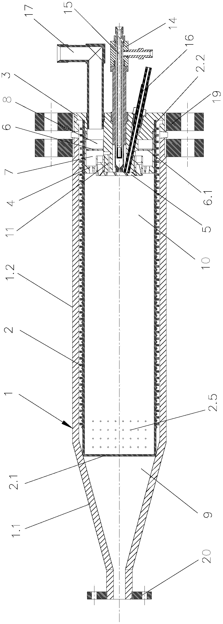
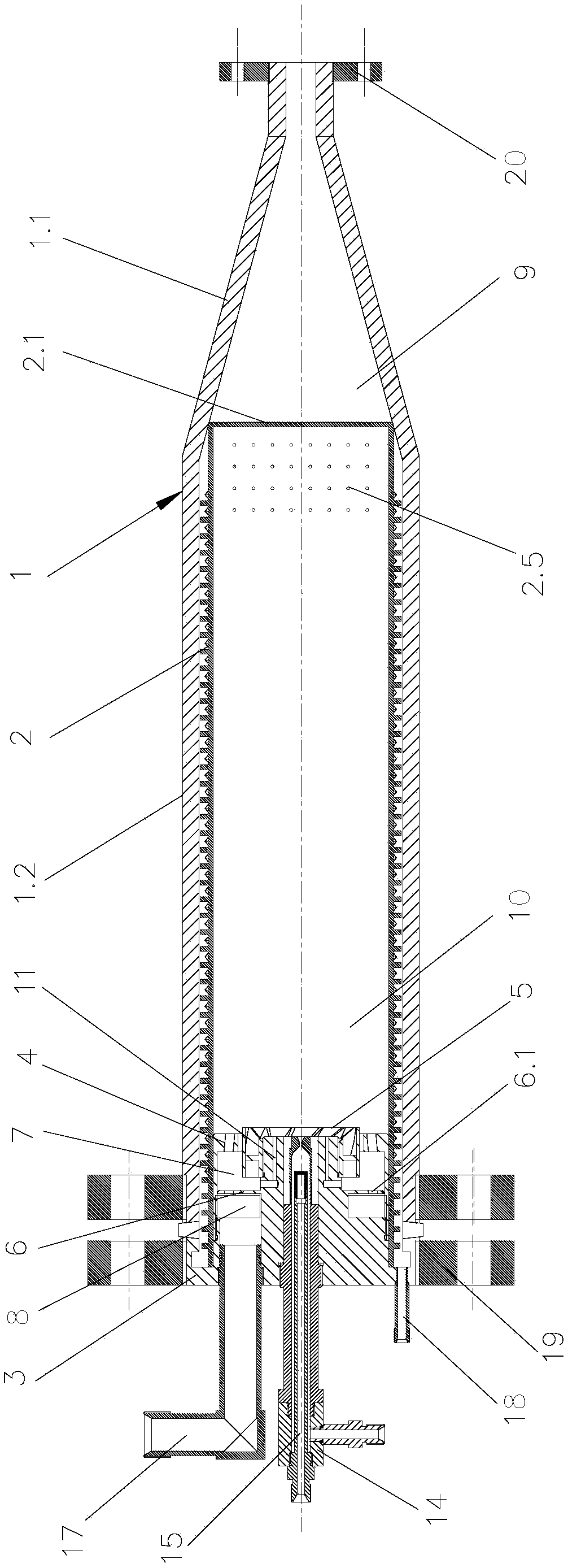
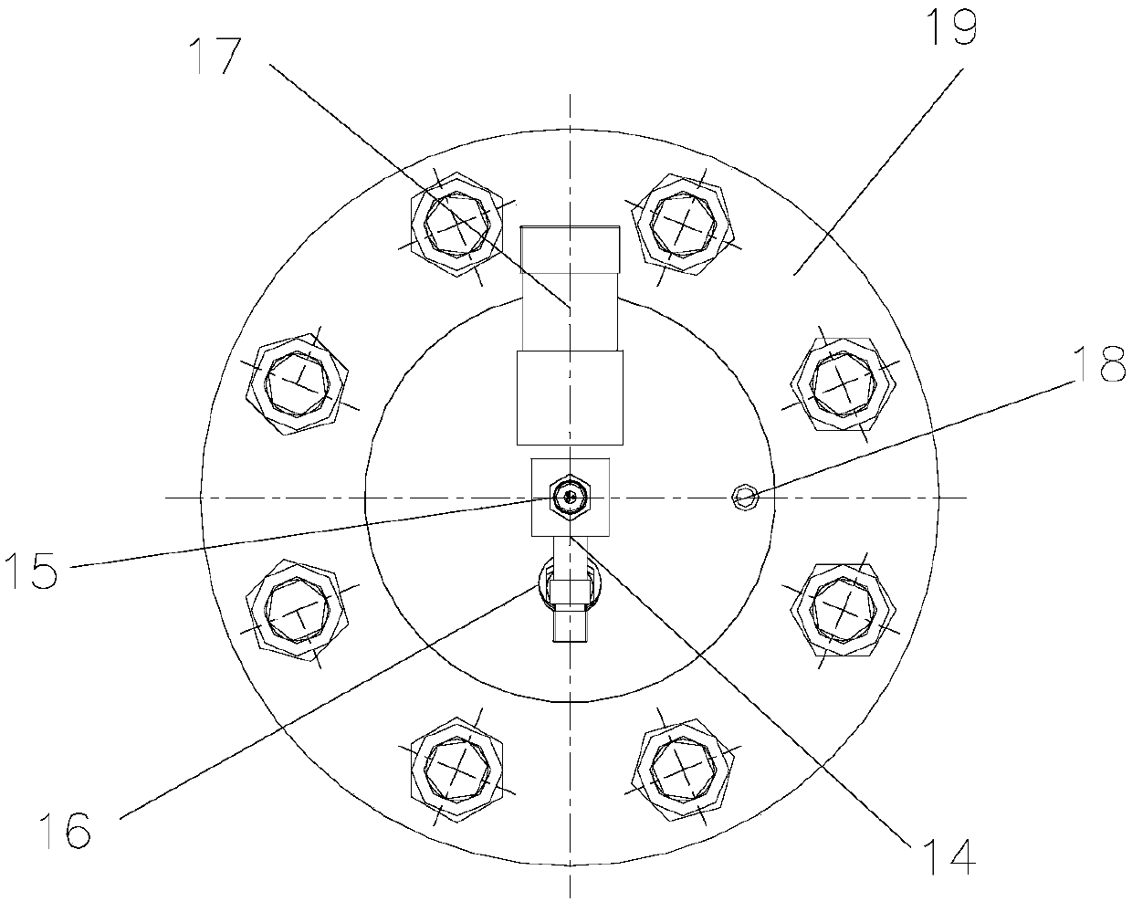
[0031] A composite heat carrier generating device suitable for high-viscosity oil shown in the figure includes a shell 1, which is integrally formed by a conical section 1.1 and a cylindrical section 1.2, and the inner wall of the shell 1 is covered with a high-temperature heat reflection layer , The outer wall of the housing 1 is covered with a high temperature heat insulation layer. The inner cavity of the housing 1 is pierced with a cooling jacket 2. The cooling jacket 2 has a closed end 2.1 and an open end 2.2. The outer wall of the cooling jacket 2 is provided with a spiral groove 2.3 extending along its axial direction. The spiral groove 2.3 The outer wall is provided with several vortex generators 2.4 staggered along its circumference, and the outer wall of the cooling jacket 2 near the closed end 2.1 is provided with several water inject...


PUM


Abstract

The invention discloses a composite heat carrier generating device suitable for high-viscosity oil. The composite heat carrier generating device comprises a shell, the shell is formed through integration of a circular cone section and a cylinder section, a cooling casing pipe is arranged in an inner cavity of the shell in a penetrating mode, and the cooling casing pipe is provided with a closed end and an open end. The closed end of the cooling casing pipe extends to and abuts against the conoid inner wall of the circular cone section, and the open end of the cooling casing pipe extends in the axial direction of the shell and penetrates out of the cylinder section to be plugged with a head body arranged at the end of the cylinder section. A cylindrical air register arranged to be opposite to the head body is arranged in an inner cavity, close to the open end, of the cooling casing pipe, and a whirlcone arranged on an external ring of the end of the head body in a sleeving mode is arranged in the middle of the air register. According to the composite heat carrier generating device, heavy oil or crude oil with the high viscosity can be burned in an atomizing mode so that the gas injection cost can be lowered, the radiation heat loss in a burning chamber is reduced at the same time, the scaling phenomenon happening in a cooling water flow pass is relieved, and the energy utilization ratio of the composite heat carrier generating device can be increased, and the operation stability of the composite heat carrier generating device are improved.

Description

technical field [0001] The invention relates to a composite heat carrier generator, in particular to a composite heat carrier generator suitable for high-viscosity oil. Background technique [0002] Multi-element thermal fluid gas injection is an oilfield thermal recovery technology emerging in recent years, and it is more and more widely used in the field of reservoir gas injection. Because the high-temperature and high-pressure multi-component thermal fluid has a combined effect of pressurization and physical and chemical viscosity reduction on the oil layer, it has a higher oil recovery rate than traditional steam thermal recovery. The composite heat carrier generating device is the core equipment of the multi-component thermal fluid gas injection system. It uses fuel and air to fully mix and burn to generate high-temperature and high-pressure flue gas, which is then mixed with water mist to form a high-temperature and high-pressure composite heat carrier, and finally inj...

Claims


Application Information

Patent Timeline
Patent Type & Authority Patents(China)
IPC IPC(8): E21B43/24E21B36/02
CPCE21B36/025E21B43/24
Inventor 周吉成冷文明陈尤平邹云张全来
Owner WUHAN YUANFANG SCI & TECH CO LTD OF CHINA SANJIANG SPACE GRP
Learn More