Power cabinet and cooling control method thereof

A technology for power cabinets and controllers, applied to electrical components, substation/distribution device casings, substation/switch layout details, etc., can solve problems such as poor contact, control component crashes, losses, etc., to achieve reasonable heat dissipation and ensure normal operation Effect

Active Publication Date: 2017-12-12
重庆鹏达电气有限责任公司
View PDF5 Cites 8 Cited by
  • Summary
  • Abstract
  • Description
  • Claims
  • Application Information

AI Technical Summary

Problems solved by technology

[0004] However, this type of power cabinet solves the problem of heat dissipation, but it causes another problem, that is, the fan, as a power unit driven by airflow, causes continuous vibration during rotation. Equipment components also have a little influence, such as easy to loosen, fall off, or poor contact of small components inside electrical equipment components, and also easily cause control components to crash. In the power control system, any link or any electrical component fails. Problems will cause the entire system to work abnormally, resulting in accidents or losses

Method used


Image

  • Power cabinet and cooling control method thereof
  • Power cabinet and cooling control method thereof
  • Power cabinet and cooling control method thereof

Examples


Embodiment 1

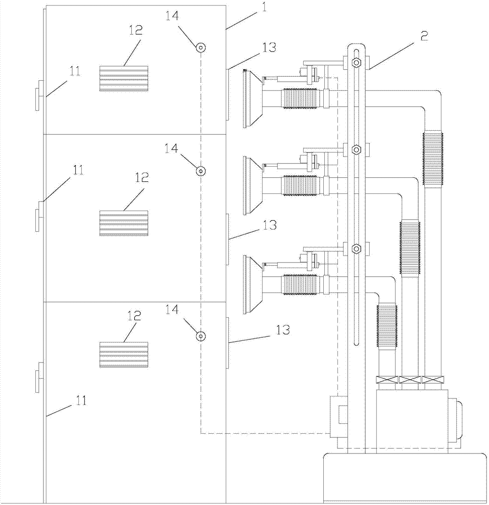
[0050] Such as figure 1 As shown, the power cabinet described in this embodiment includes a cabinet body 1 composed of N independent chambers 11 and an external heat sink 2 located on the rear side of the cabinet body 1, and each chamber 11 is provided with an air inlet window 12 And the air outlet 13, in normal times, the air inlet window 12 and the air outlet 13 can overflow hot air outwards so as to achieve the purpose of heat dissipation, the air outlet 13 is opposite to the external cooling device 2, and each chamber 11 is also provided with Temperature probe 14; It is characterized in that:

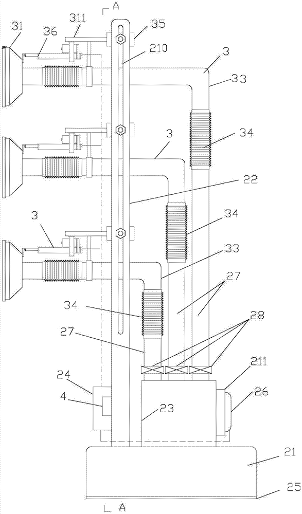
[0051] Such as figure 2 , 4 As shown, the external cooling device 2 includes a chassis 21, a bracket 22, a bellows 23, a control box 24 and N exhaust devices 3 installed on the bracket 22, each exhaust device 3 corresponds to an air outlet 13, and the chassis 21 bottom surfaces have buffer pad 25, and the effect of buffer pad 25 is to absorb the vibration that blower fan 26 prod...

Embodiment 2

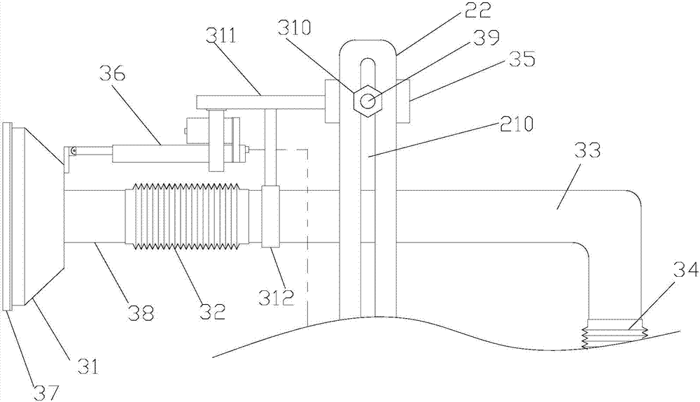
[0059] Such as Figure 5 As shown, the power cabinet described in this embodiment is substantially the same as that in Embodiment 1, the difference is that: the suction cover 31 is provided with a position sensing switch 5, and the signal of the position sensing switch 5 is also input to the controller 4. The position sensing switch 5 can sense the cabinet body. When it senses that there is a small distance X from the cabinet body (at this time, the sealing ring 37 just fits, and at the same time, the sealing ring 37 is not excessively deformed to affect the buffering capacity), The controller can stop the propulsion work of the telescopic driver 36, and the setting of this small distance X can be realized by adjusting the detection range of the position sensing switch 5, which belongs to the prior art, such as the proximity switch of Schneider or Omron; The sealing ring 37 has a plurality of inner and outer sealing lips; firstly, the plurality of sealing lips have a good seal...

Embodiment 3

[0061] Such as Figure 6 , 7 As shown, the power cabinet described in this embodiment is substantially the same as that of Embodiment 1, the difference lies in: the structure and arrangement of the sealing ring 37, that is, the front port of the suction cover 31 is provided with a ring groove 6 along the outside, The sealing ring 37 is composed of a C-shaped ring pipe section 61 and two annular pins 62, and the two annular pins 62 are located in the annular groove 6 and fastened by screws 63; such a sealing ring 37 is Hollow and easy to deform, the C-shaped ring pipe section 61 will be flattened after it contacts the cabinet body, forming a larger sealing surface, which can effectively improve the sealing performance, and at the same time, because of its hollow structure, it can effectively absorb vibration and reduce the transmission of vibration .


PUM


Abstract

Disclosed in the invention is a power cabinet comprising a cabinet body formed by N independent cavities and an external cooling device arranged at the rear side of the cabinet body. Each cavity is provided with an inlet window and an air outlet; the air outlet is opposite to the external cooling device; and a temperature probe is also arranged inside each cavity. The external cooling device consists of a base plate, a support, an air box, a control box, and N exhausting units installed on the support; each exhausting unit corresponds to one air outlet; and the exhausting units include suction hoods, telescopic tubes I, L-shaped elbow pipes, telescopic tubes II, sliding blocks, and telescopic drivers. Compared with the prior art, the power cabinet has the following beneficial effects: no fan is arranged in the cabinet body and hot air inside the cabinet body is exhausted by the external cooling device; the draught fan as an air flow power unit is arranged isndie the external cooling device and a few part of vibration caused by the fan can be transmitted to the cabinet body, so that the influence caused by fan vibration is reduced and thus electrical equipment elements work normally. In addition, the invention also designs a cooling control method of the power cabinet.

Description

technical field [0001] The invention relates to an electric device, in particular to a power cabinet and a heat dissipation control method thereof. Background technique [0002] Power cabinets are commonly used electrical equipment. Electrical cabinets, switch cabinets, power distribution cabinets, etc. all belong to this category. The function of the power cabinet is to serve as a carrier for electrical equipment components. Components will generate heat when they are working, which will increase the temperature inside the power cabinet. When the temperature inside the power cabinet is too high, the working stability of electrical equipment components will decrease. For example, the PLC and single-chip microcomputer as the control core will easily cause the processing speed to drop. Or in the case of a crash, in addition, other electrical equipment components will also affect their service life due to long-term high temperature. Therefore, the power cabinet needs to dissipa...

Claims


Application Information

Patent Timeline
Patent Type & Authority Applications(China)
IPC IPC(8): H02B1/56H02B1/30
CPCH02B1/30H02B1/306H02B1/565
Inventor 王涛高明
Owner 重庆鹏达电气有限责任公司
Why Eureka
Try Eureka