
Cross-linked polyethylene insulated cable insulation shielded isolation joint and mold casting manufacturing process thereof

A cross-linked polyethylene and insulation shielding technology, which is applied in the direction of connecting/terminating cable equipment, etc., can solve the problems of interface polarization, insulation breakdown, and large contact resistance at the connection, so as to break through the technical bottleneck and avoid breakdown Problems, effects of electrical performance stabilization

Active Publication Date: 2017-12-12
CHANGYUAN ELECTRIC TECH
View PDF9 Cites 5 Cited by
  • Summary
  • Abstract
  • Description
  • Claims
  • Application Information

AI Technical Summary

Problems solved by technology

[0004]The wire cores of this type of connector are mostly mechanically connected by crimping or bolt twisting, and the contact resistance at the connection is relatively high, which is easy to cause heat; There is an active interface between the insulation and the cable main body, and the active interface contains complex factors such as micro air gaps, micro water, impurities, and insulating grease, which can easily lead to interface polarization and air gap discharge along the surface; there is a fixed interface in the insulation shielding isolation part , there is an air gap microscopically in the fixed interface, and the air gap causes partial discharge, which eventually leads to insulation breakdown, which restricts the safe operation of the cable system

Method used


Image

  • Cross-linked polyethylene insulated cable insulation shielded isolation joint and mold casting manufacturing process thereof
  • Cross-linked polyethylene insulated cable insulation shielded isolation joint and mold casting manufacturing process thereof
  • Cross-linked polyethylene insulated cable insulation shielded isolation joint and mold casting manufacturing process thereof

Examples


Embodiment Construction

[0017] The following will clearly and completely describe the technical solutions in the embodiments of the present invention with reference to the accompanying drawings in the embodiments of the present invention. Obviously, the described embodiments are only some, not all, embodiments of the present invention. Based on the embodiments of the present invention, all other embodiments obtained by persons of ordinary skill in the art without making creative efforts belong to the protection scope of the present invention.

[0018] XLPE insulated cables on the market usually include the following layers in sequence: conductor core, inner semiconductive layer, XLPE insulation layer (main insulation layer), outer semiconductive layer, metal sheath and PVC / PE outer sheath. The manufacturing process of the present invention is used to overcome the problem of electric field distortion at the isolation point of the insulation shielding isolation joint, and prevent the point from being ...


PUM


Abstract

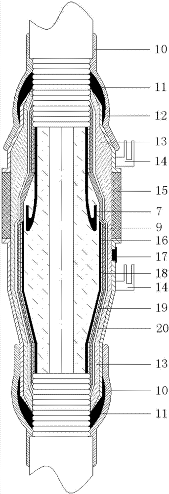
The invention provides a cross-linked polyethylene insulated cable insulation shielded isolation joint and a mold casting manufacturing process thereof. The cross-linked polyethylene insulated cable sequentially at least comprises a conductor cable core, an inner semi-conducting layer, a main insulating layer and an outer semi-conducting layer from the interior to exterior. The mold casting manufacturing process is characterized by comprising the following steps: stripping various layers at the cable end; welding conductor wire cores; restoring the main insulating layer; restoring the outer semi-conducting layer. The insulation shielded isolation joint comprises a stress control module. The manufacturing process disclosed by the invention is convenient to operate, and the manufactured insulation shielded isolation joint forms an integral structure with a cable body; electric stress distribution has stable electrical property, and the problem that cable insulation breakdown is caused by air-gap discharge on an insulated junction due to an active interface is generated by different materials between the cable and the stress control module is solved.

Description

technical field [0001] The invention relates to the technical field of electric wires and cables, in particular to a cross-linked polyethylene cable insulation shielding isolation joint and its molding process. Background technique [0002] When the high-voltage XLPE cable line is long or the cable line has an overvoltage or short-circuit fault, a high induced voltage will be formed on the metal sheath, which will cause breakdown of the cable outer sheath insulation, so XLPE should be used The cable insulation shield isolation joint completely disconnects the cable insulation shield (outer semi-conductive layer, metal sheath), in order to complete the cross-transposition of the cable insulation shield (outer semi-conductive layer, metal sheath) to reduce the induced voltage and circulating current in the line , which is conducive to improving the transmission capacity of the cable. The electric field at the cut-off point of the outer semi-conductive layer of the high-voltag...

Claims


Application Information

Patent Timeline
IPC IPC(8): H02G1/14
CPCH02G1/14Y02A30/14
Inventor 胡飞强卫刘夏黄成龙张俊杰梁振杰夏云杰
Owner CHANGYUAN ELECTRIC TECH
Learn More