
Hybrid power driving cylinder capable of magnifying multi-fold driving force

A hybrid and driving force technology, applied in the field of blow molding machines, can solve the problems of insufficient clamping force, affecting running speed and high cost, and achieve the effect of improving market competitiveness, improving production efficiency and low production cost

Active Publication Date: 2017-12-15
GUANGDONG LESHAN INTELLIGENT EQUIP CORP LTD
View PDF16 Cites 1 Cited by
  • Summary
  • Abstract
  • Description
  • Claims
  • Application Information

AI Technical Summary

Problems solved by technology

Whether it is single-cylinder or multi-cylinder mold clamping, the disadvantage is that the use of clamping cylinders requires extremely high sealing conditions, and mold clamping is prone to oil leakage and pressure relief, resulting in insufficient clamping force, so the processing of parts is difficult and costly. , assembly and maintenance are difficult, and the greater the clamping force, the greater the radius of the required clamping cylinder, the more difficult the sealing, the more difficult the control of the oil circuit, and the more hydraulic oil used, plus the oil cylinder itself. The greater the mass, the greater the movement quality, and the greater the power required for frequent mold opening and closing movements, so it is difficult to apply to large-tonnage injection molding machines. At the same time, the maximum stroke of the movable platen can only reach the length of the clamping cylinder, and the longer the stroke , the longer the clamping cylinder, the greater the movement quality. The frequent reciprocating movement of the hydraulic oil during the mold opening and closing process affects the running speed, and it is easy to increase the oil temperature and accelerate the aging of the sealing ring, and a large amount of hydraulic oil is discarded when the machine is scrapped. will cause serious environmental pollution

Method used


Image

  • Hybrid power driving cylinder capable of magnifying multi-fold driving force
  • Hybrid power driving cylinder capable of magnifying multi-fold driving force

Examples


Embodiment Construction

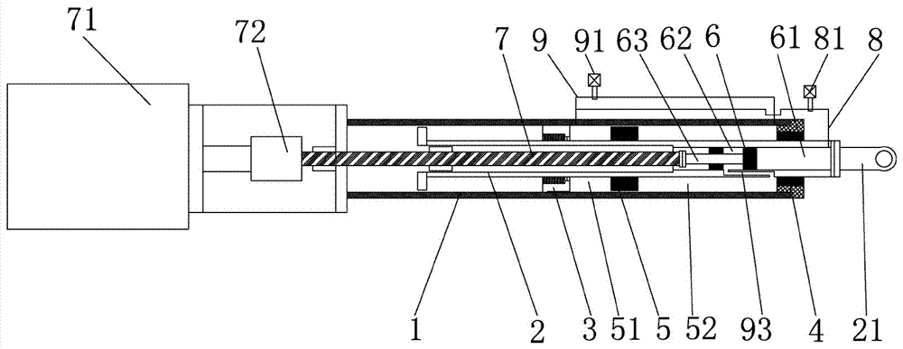
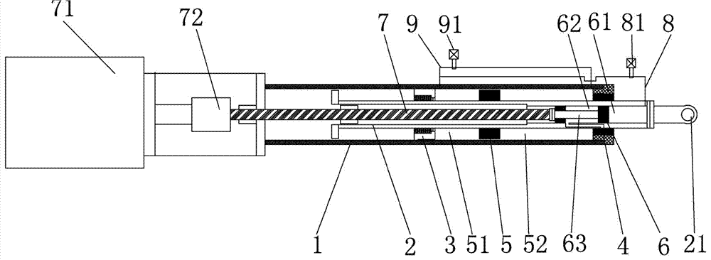
[0016] The present invention will be specifically and further described below in conjunction with the accompanying drawings. A hybrid driving cylinder capable of amplifying multiple driving forces, characterized in that it includes a low-pressure sleeve 1 and a high-pressure sleeve 2, the high-pressure sleeve 2 is installed in the low-pressure sleeve 1, and is mounted on the column of the high-pressure sleeve 2 The first sealing guide sleeve 3 and the second sealing guide sleeve 4 are installed between the surface and the inner hole of the low-pressure sleeve 1, so that the high-pressure sleeve 2 can move axially relative to the low-pressure sleeve 1;

[0017] The first sealing guide sleeve 3 and the second sealing guide sleeve 4 form a closed low-pressure oil chamber with the low-pressure sleeve 1 and the high-pressure sleeve 2, and the low-pressure piston 5 installed on the cylindrical surface of the high-pressure sleeve 2 drives the oil chamber Divided into low-pressure dri...


PUM


Abstract

A hybrid power driving cylinder capable of magnifying multi-fold driving force is characterized in that the hybrid power driving cylinder comprises a low-pressure sleeve and a high-pressure sleeve, the high-pressure sleeve is mounted in the low-pressure sleeve, and a first sealing guide cover and a second sealing guide cover are mounted between the cylinder surface of the high-pressure sleeve and an inner hole of the low-pressure sleeve, so that the high-pressure sleeve can axially move relative to the low-pressure sleeve; the first sealing guide cover and the second sealing guide cover as well as the low-pressure sleeve and the high-pressure sleeve form a sealed low-pressure oil cavity; and a low-pressure piston mounted on the cylinder surface of the high-pressure sleeve divides the oil cavity into a low-pressure driving cavity and a low-pressure oil return cavity. The hybrid power driving cylinder has the beneficial effects that according to the Pascal law, a high-pressure piston with the small effective action area is used to push the low-pressure piston with the large effective action area to move, and thus only a driving screw rod needs to provide small thrust, a low-pressure piston cylinder can produce the large pressure used for a locking mould.

Description

technical field [0001] The invention relates to the technical field of a blow molding machine, in particular to a hybrid driving cylinder capable of multiplying the driving force. Background technique [0002] At present, the injection molding machines and blow molding machines used at home and abroad are generally in the toggle lock mode and hydraulic lock mode. The injection molding machine using the toggle mechanism uses the elastic deformation force of the hinged toggle when the toggle is straightened to lock the mold. There are many hinged toggles and hinge points, so the force length cannot be guaranteed to be equal during manufacture and assembly. At the same time, a large amount of lubricating oil and a complex lubrication system are required. Long running time will easily lead to wear and tear, resulting in structural imbalance. Large, and accelerated wear, forming a vicious circle, resulting in crawling phenomenon in the opening and closing of the movable platen, i...

Claims


Application Information

Patent Timeline
Patent Type & Authority Applications(China)
IPC IPC(8): B29C45/68
CPCB29C45/68B29C2045/685Y02T10/62
Inventor 郭锡南
Owner GUANGDONG LESHAN INTELLIGENT EQUIP CORP LTD
Learn More