
Gravity casting simulation test stand

A simulation test bench, gravity casting technology, which is used in testing metals, teaching models, foundry workshops, etc., can solve the problem of not meeting the needs of gravity casting simulation tests for casting molding, lack of indoor gravity casting simulation test devices, and inability to perform casting law simulation tests. and other problems, to achieve the effect of compact structure, low cost and strong practicability

Active Publication Date: 2017-12-15
ANHUI UNIV OF SCI & TECH
View PDF14 Cites 4 Cited by
  • Summary
  • Abstract
  • Description
  • Claims
  • Application Information

AI Technical Summary

Problems solved by technology

Zhao Zhongxing, Jin Guang, Wang Yongchen, Wang Lianqi and others published a paper titled "Development of a Multifunctional Water Simulation Test Bench" in the second issue of "Thermal Processing Technology" in 2003. Introduced a water simulation test bench, including a workbench, a low-pressure casting Water tank, main water tank, water supply pump, auxiliary water tank, measuring water tank, circulating water pump, pouring water tank, flow regulating pipe, lifting mechanism, mobile trolley, flow rate meter, the mobile trolley and the water tank above it can move back and forth, left and right, and the lifting of the pouring water tank is controlled by wire The rod and the screw nut with the runner are realized manually. This test bench can be used for the measurement of the flow coefficient and the filling test, but it cannot be used for the simulation test of the casting rule.
[0006] The obvious disadvantage of the existing technology is that there is a lack of effective indoor gravity casting simulation test equipment, especially the lack of comprehensive test benches that can simultaneously carry out gravity casting law simulation tests, filling process hydraulic simulation tests and vibration casting tests, which are more affected by the environment. Large, less measurable parameters, and inconvenient operation, cannot meet the needs of gravity casting simulation tests for casting molding, and cannot make targeted test and research plans according to various working conditions

Method used


Image

  • Gravity casting simulation test stand
  • Gravity casting simulation test stand
  • Gravity casting simulation test stand

Examples


Embodiment Construction

[0024] In order to make the technical means, creative features, objectives and effects achieved by the present invention easy to understand, the present invention will be further described below in conjunction with specific embodiments and illustrations.

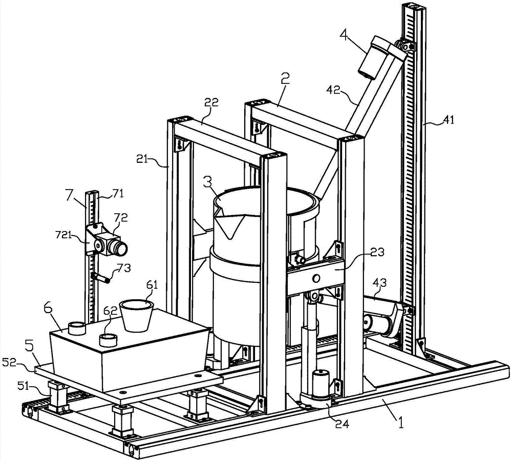
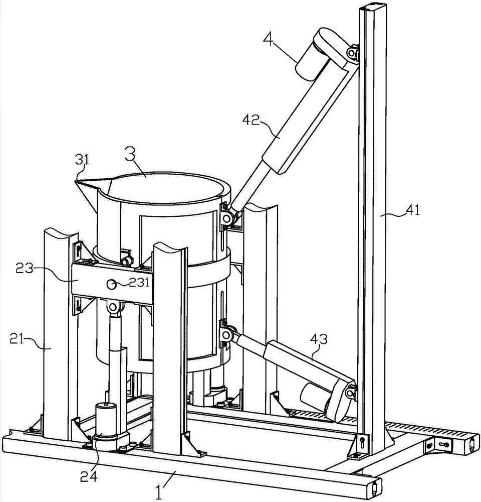
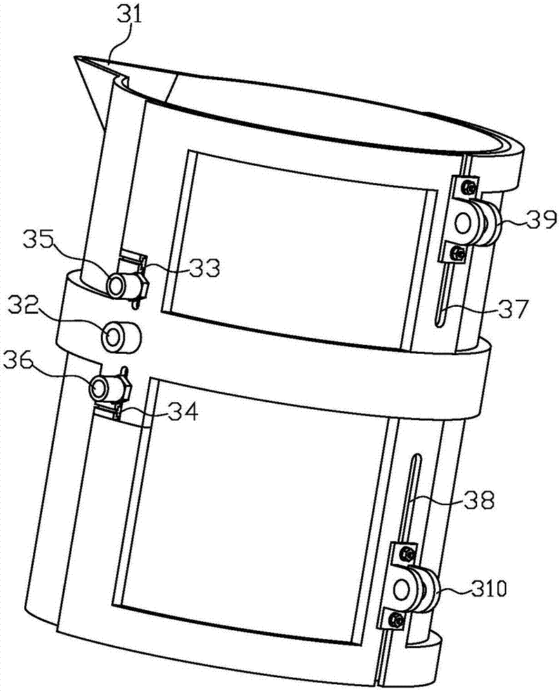
[0025] Such as figure 1 , figure 2 , image 3 with Figure 4 As shown, a gravity casting simulation test bench includes a base 1 , a ladle frame 2 , a test ladle 3 , a pouring device 4 , a vibrating table 5 , a simulation sand box 6 and a measuring device 7 . Wherein, the ladle frame 2 is located in the middle of the base 1, and is fixedly connected with the base 1 by screws; the test ladle 3 is installed on the ladle frame 2, and both sides of the test ladle 3 are connected to the ladle The frame 2 is connected by a hinge; the pouring device 4 is located at the rear of the base 1, the bottom of the pouring device 4 is fixed on the base 1 by screws, and the front end of the pouring device 4 passes through the test ladle ...


PUM


Abstract

The invention discloses a gravity casting simulation test stand. The test stand comprises a base, a casting ladle frame, a test casting ladle, a dumping device, a vibrating table, a simulating sand box and a measuring device. By selecting water or slurry or glycerin or the like as a medium to simulate liquid metal, the gravity casting simulation test stand is mainly used for hydraulic simulation tests in the filling process, casting rule simulation tests and vibration casting simulation tests in the casting molding process. The test casting ladle is driven by the dumping device to achieve gravity casting, and different casting systems and moulds are installed in the simulating sand box to carry out filling tests; test results can be obtained by sensors installed in the measuring device, the vibrating table, the simulating sand box and the test casting ladle, and test parameters can be automatically collected and converted by a computer. According to different working conditions and the different casting systems and moulds, a test scheme is made in a targeted mode, a regular conclusion is obtained, and the test stand has the advantages that researches are not limited by environment, sites and other factors, and the test stand is easy to operate, low in cost and the like.

Description

technical field [0001] The invention belongs to the technical field of casting test equipment, in particular to a gravity casting simulation test bench. Background technique [0002] In traditional casting production, casting process parameters such as flow coefficient and flow rate and reasonable gating system are still determined based on experience, which is not enough and unscientific for some important and complex castings with large batches, and the rejection rate of castings is high. If not, it often results in significant economic losses. During casting in foundry production, molten iron or steel needs to be transferred to the production line with a ladle, and the molten iron or molten steel in the ladle is poured into the sprue cup of the casting workpiece by aligning with the sprue. After cooling, it is cleaned by falling sand to form a casting. At present, the casting of molten iron or molten steel is carried by the workers by hand or by driving a heavy ladle, an...

Claims


Application Information

Patent Timeline
IPC IPC(8): G01N33/20G09B25/02
CPCG09B25/02G01N33/205G09B25/025B22D45/00B22D46/00B22D47/00B22D37/00
Inventor 王成军窦海石郑艳李龙郭永存沈豫浙余汉伟
Owner ANHUI UNIV OF SCI & TECH
Learn More