An intelligent soil gas-flux monitoring system and monitoring method

A soil gas and monitoring system technology, applied in soil material testing, measuring devices, instruments, etc., can solve the problems of uneven air chamber pressure, low degree of automation, and poor compatibility, and achieve a high degree of automation, fast response, and compact structure Effect

Pending Publication Date: 2017-12-15
赵明春 +1
View PDF12 Cites 14 Cited by
  • Summary
  • Abstract
  • Description
  • Claims
  • Application Information

AI Technical Summary

Problems solved by technology

[0005] The purpose of the present invention is to provide an intelligent soil gas flux monitoring system and monitoring method to solve the problems of uneven gas chamber pressure, high energy consumption, poor adaptability, low precision, poor compatibility, and low degree of automation of the flux measuring instrument.

Method used


Image

  • An intelligent soil gas-flux monitoring system and monitoring method
  • An intelligent soil gas-flux monitoring system and monitoring method
  • An intelligent soil gas-flux monitoring system and monitoring method

Examples


Embodiment Construction

[0037] The technical solution in this description will be described in detail in combination with specific implementation methods.

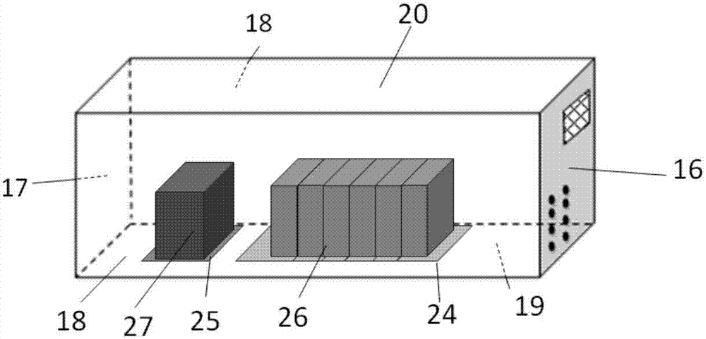
[0038] An intelligent soil gas flux monitoring system includes a main box and a data acquisition system.

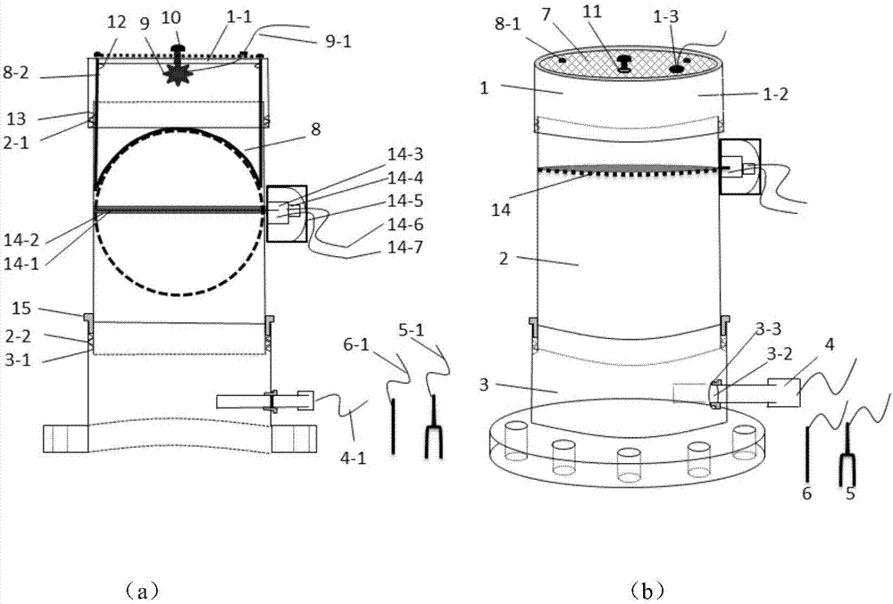
[0039] Such as figure 1 As shown in (a)~(b), the data acquisition system includes an air chamber, a carbon dioxide sensor 4, a humidity sensor 5, and a temperature sensor 6; the air chamber includes an insect-proof net cover 1, and a cylinder 2 equipped with an automatic control function gate 14 (hereinafter referred to as cylinder 2), flange 3, and cylinder 2 is installed between insect-proof net cover 1 and flange 3 to form an air chamber.

[0040] The automatic control function flashboard 14 includes an airtight partition 14-1, a bearing 14-2, a flashboard motor 14-3, a signal control unit 14-4, a protective cover 14-5, a flashboard signal line 14-6, a gate board power cord 14-7. The airtight partition 14 - 1 is circular, located insid...


PUM


Abstract

An intelligent soil gas-flux monitoring system and monitoring method are disclosed. The system includes a host box and a data collection system. The data collection system includes a gas chamber, a carbon dioxide sensor, a humidity sensor and a temperature sensor. The gas chamber includes an insect-proof net cover, a cylinder provided with an automatically controlled functional gate plate, and a flange. The cylinder is mounted between the insect-proof net cover and the flange. The carbon dioxide sensor is mounted on the flange at the bottom of the gas chamber. A measuring end of the carbon dioxide sensor protrudes into the gas chamber. A measuring end of the temperature sensor is in the environment surrounding the gas chamber. A measuring end of the humidity sensor is inserted into soil surrounding the gas chamber. The carbon dioxide sensor, the humidity sensor and the temperature sensor are connected to the host box. A problem that air flow rate measurement is required for CO2 flux calculation is avoided. Connection between the gas chamber and the host box with an air pipe is not needed, thus avoiding air blockage in an air pipe aeration process and an air pressure balance problem in the gas chamber. Sealed gas measurement and opened air change and circulation are adopted, and long-term continuous automatic monitoring can be achieved.

Description

technical field [0001] The invention relates to the technical fields of safety, environmental protection and gas detection, in particular to an intelligent soil gas flux monitoring system and a monitoring method. Background technique [0002] With the acceleration of the industrialization process of society in the past century, CO in the atmosphere 2 The concentration is increasing, and the greenhouse effect caused by it has led to serious environmental and ecological problems such as global warming, glacier melting, and sea level rise. On the basis of vigorously controlling the source of carbon emissions and reducing carbon emissions, CO 2 Capture, utilization and storage (CCUS) has become a widely concerned method to suppress atmospheric CO 2 One of the effective ways to increase the concentration. [0003] The prerequisite for the realization of CCUS technology is to establish a CO 2 The geological storage process and the safety and environmental impact assessment sys...

Claims


Application Information

Patent Timeline
Patent Type & Authority Applications(China)
IPC IPC(8): G01N33/24G01D21/02
CPCG01D21/02G01N33/24G01N33/246
Inventor 赵明春佐佐木久郎
Owner 赵明春
Why Eureka
Try Eureka