Eureka AIR delivers breakthrough ideas for toughest innovation challenges, trusted by R&D personnel around the world.

Unit motor modular consequent pole permanent magnet synchronous linear motor

A permanent magnet synchronous linear and motor module technology, used in electrical components, electromechanical devices, electric components, etc., can solve the problems of continuous pole permanent magnet synchronous linear motor thrust fluctuation, etc., to suppress end effects, reduce volume and mass, The effect of increasing thrust density

Active Publication Date: 2017-12-15
NANJING UNIV OF AERONAUTICS & ASTRONAUTICS
View PDF4 Cites 4 Cited by
  • Summary
  • Abstract
  • Description
  • Claims
  • Application Information

AI Technical Summary

Problems solved by technology

[0003] In order to solve the large thrust fluctuation problem of the existing continuous pole permanent magnet synchronous linear motor, the present invention proposes a unit motor modular continuous pole permanent magnet synchronous linear motor

Method used


Image

  • Unit motor modular consequent pole permanent magnet synchronous linear motor
  • Unit motor modular consequent pole permanent magnet synchronous linear motor
  • Unit motor modular consequent pole permanent magnet synchronous linear motor

Examples


Embodiment approach 1

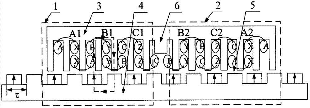
[0022] Such as figure 1 , 2, 3, 4, 5, the unit motor modular continuous pole permanent magnet synchronous linear motor includes unit motor one 1 and unit motor two 2, and each unit motor includes a primary assembly 3 and a secondary assembly 4. The primary assembly 3 consists of a primary yoke 3-1, a primary tooth 3-2 and an armature winding 3-4, which is arranged in the slot 3-3. The secondary assembly 4 is composed of permanent magnets 4-1, iron poles 4-2 and secondary yokes 4-3, the permanent magnets and iron poles are arranged alternately, and the magnetization direction of all permanent magnets is the same. An air gap 5 exists between the primary assembly 3 and the secondary assembly 4 . Between the unit motor one 1 and the unit motor two 2, a magnetic modulation structure 6 is arranged. The magnetic modulation structure 6 is made of a magnetic permeable material, and is integrally formed with the primary yoke 3-1. On the magnetic adjustment structure 6, the width of th...

Embodiment approach 2

[0026] Such as Image 6 As shown, the motor adopts three unit motor structures, a magnetic modulation structure 10 is arranged between the first unit motor 7 and a second unit motor 8, and a magnetic modulation structure 11 is arranged between the second unit motor 8 and the third unit motor 9. The phase sequence of the windings on unit motor one 7 is arranged in accordance with phase A winding-phase B winding-phase C winding. The upper windings of unit motor 2 8 are set according to B-phase winding-C-phase winding-A-phase winding. The upper winding of unit motor three 9 is according to C phase winding-A phase winding-B phase winding.


PUM


Abstract

The invention provides a unit motor modular consequent pole permanent magnet synchronous linear motor and belongs to the motor technical field. The unit motor modular consequent pole permanent magnet synchronous linear motor is composed of a plurality of unit motors; each unit motor includes a primary assembly and a secondary assembly; the primary assembly is composed of a primary iron core and an armature winding, wherein the primary iron core is slotted, and the armature winding is arranged in the slots of the primary iron core; the secondary assembly is composed of permanent magnets, iron poles and a yoke plate, wherein the iron poles and yoke plate are integrally modeled; an air gap is left between the primary assembly and the secondary assembly; a magnetic adjusting structure is arranged between two adjacent unit motors; the width of the magnetic adjusting structure can be expressed as an equation that S=(k+2 / 3)tau, wherein k is an integer, and tau is the pole pitch of the motors; and the arrangement sequences of the windings in the slots of the two adjacent motor units are different. With the structure adopted, the suppression of an end portion effect can be benefitted, the asymmetry of the three-phase windings of the permanent magnet synchronous linear motor can be improved, and thrust ripples can be decreased.

Description

technical field [0001] The invention belongs to the field of motors, in particular to a unit motor modularized continuous pole permanent magnet synchronous linear motor. Background technique [0002] Permanent magnets and iron poles arranged alternately are used on the secondary side of the continuous pole permanent magnet synchronous linear motor, which greatly reduces the amount of permanent magnets used in the long secondary structure linear motor and saves costs. The continuous pole structure can reduce the electromagnetic attraction between the primary and secondary of the motor by 40% to 50%, thereby reducing the thickness of the motor support structure, reducing the volume of the motor and increasing the thrust density. However, the linear motor itself has cogging effect and end effect, and because the continuous pole structure adopts permanent magnets and iron poles, the magnetic field distortion is relatively large, and more harmonic components are generated, result...

Claims


Application Information

Patent Timeline
IPC IPC(8): H02K41/03
Inventor 李静黄旭珍钱振宇
Owner NANJING UNIV OF AERONAUTICS & ASTRONAUTICS
Why Eureka
Eureka Blog
Learn More