Constant-force floating system

A technology of constant force and floating shaft, which is applied in fluid pressure actuation system testing, fluid pressure actuation system components, fluid pressure actuation devices, etc. It can solve the problem of poor implementation of constant force control and difficulty in achieving constant force grinding , the complex structure of the device to be polished, etc., to achieve the effects of excellent flow regulation dynamic performance, excellent gas circuit exchange integration, and fast response

Active Publication Date: 2017-12-22
SUNRISE INSTR CO LTD
View PDF12 Cites 11 Cited by
  • Summary
  • Abstract
  • Description
  • Claims
  • Application Information

AI Technical Summary

Problems solved by technology

Due to the complex structure of the device to be polished, it is also very difficult to control the entire system. In particular, it is necessary to achieve constant force grinding. Due to the lack of constant force devices and the poor implementation of constant force control, it is difficult to achieve constant force grinding in industry.

Method used


Image

  • Constant-force floating system
  • Constant-force floating system
  • Constant-force floating system

Examples


Embodiment 1

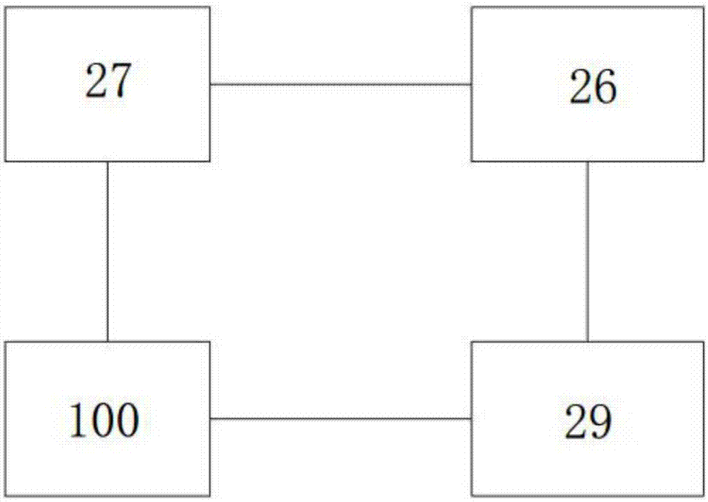
[0052] Please refer to Figure 1 to Figure 13 , the present invention provides a constant force floating system, including a controller 27 , a constant force floating unit 29 , an electric servo valve 100 and a force sensor 26 .

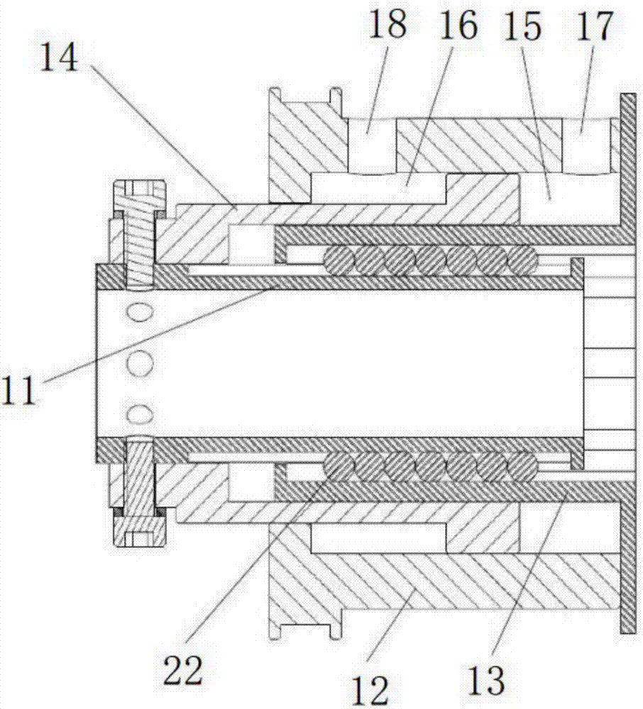
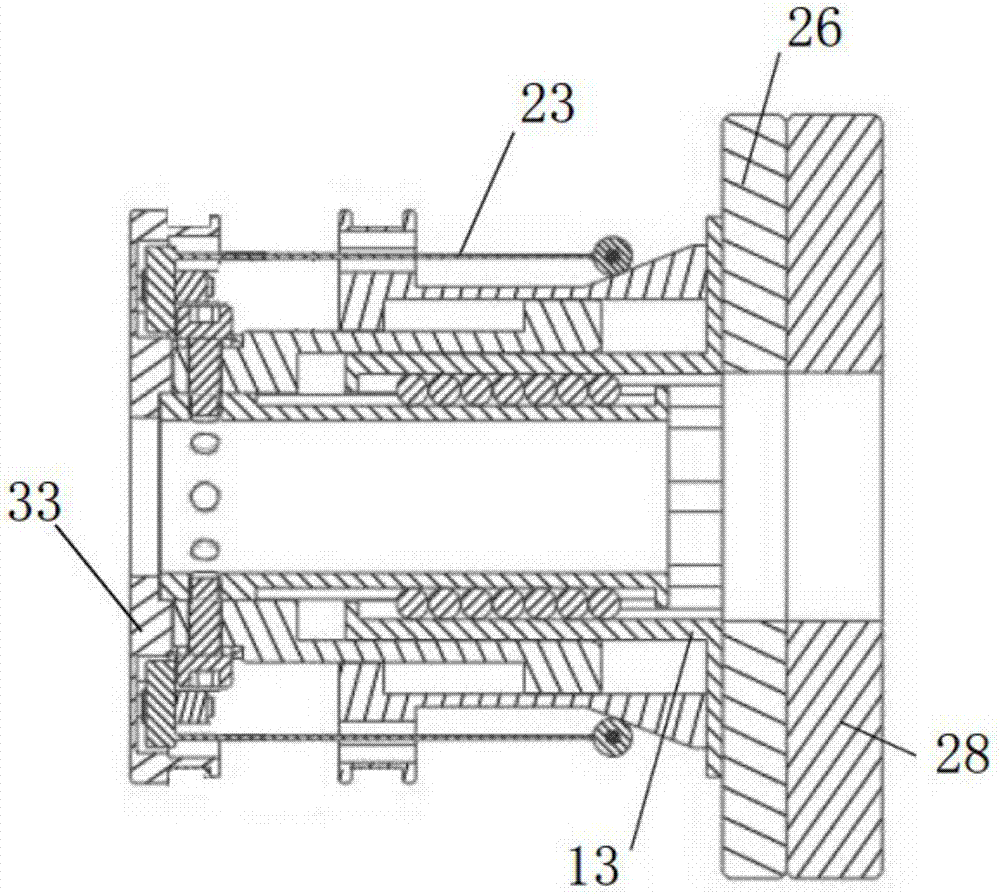
[0053] Please refer to figure 2 , the constant force floating unit 29 is an axial floating unit, and the axial floating unit includes a floating shaft 11, a constant pressure outer cylinder 12, a constant pressure inner cylinder 13 and a floating piston 14: a constant pressure inner cylinder 13 and a floating piston 14 They are respectively sleeved on the outside of the floating shaft 11. The constant pressure outer cylinder 12 is sleeved on the outside of the constant pressure inner cylinder 13 and the floating piston 14. A cavity is formed between the constant pressure outer cylinder 12 and the constant pressure inner cylinder 13. One end of the floating piston 14 is fixedly connected to the floating shaft 11, and the other end is located in the ...

Embodiment 2

[0079] This embodiment provides a constant force floating system. The difference from Embodiment 1 is that the constant force floating unit 29 in this embodiment is a radial floating unit.

[0080] Please refer to Figure 14, the radial floating unit includes a cylinder barrel 1, a piston 2, a universal bearing 3, a support barrel 4, a bearing claw 5, a support seat 6 and a force claw 7, and the cylinder barrel 1 is sleeved outside the piston 2 and connected to the piston 2 An air chamber 8 is formed, the cylinder barrel 1 is provided with a third air inlet 9, the third air inlet 9 communicates with the air chamber 8, and the support seat 6 is fixedly connected to the bottom end of the cylinder barrel 1; the universal bearing 3 is set At the center of the support base 6, the universal bearing 3 is equipped with a support cylinder 4 matching the universal bearing 3; the force bearing claw 5 is fixedly connected with the support cylinder 4, and the force claw 7 is fixedly connec...

Embodiment 3

[0088] Please refer to Figure 16 , the present embodiment provides a constant force floating system. The difference from Embodiment 1 and Embodiment 2 is that the constant force floating unit 29 in this embodiment includes an axial floating unit and a radial floating unit, and the axial floating unit and The specific connection relationship of the radial floating unit is that the floating shaft 11 of the axial floating unit is fixedly installed on the side wall of the radial floating unit through a connecting piece such as a flange 33 . Of course, there are other styles of the positional relationship and connection relationship between the axial floating unit and the radial floating unit in the present invention, and this embodiment is only one of them. There are two electric servo valves 100, which respectively provide air flow to the axial floating unit and the radial floating unit. Please refer to Embodiment 1 for the structure of the electric servo valve 100. For the spe...


PUM


Abstract

The invention discloses a constant-force floating system, and relates to the technical field of industrial automatic equipment. The constant-force floating system comprises a controller, a constant-force floating unit, an electric servo valve and a force sensor. The constant-force floating unit can achieve constant-force work, the force sensor can detect constant force and transmits the constant force information to the controller, and the controller conducts active adjustment or makes a decision according to the sensor information to control the electric servo valve so as to control flow input into the constant-force floating unit for constant force adjustment. According to the constant-force floating system, the constant force of the constant-force floating unit can be actively controlled through the controller preset program, real-time adjustment can be conducted according to feedback during using, operation of multiple situations can be achieved, the controllable degree is high, the adjusting speed is high, and precise grinding, cutting and other technology machining are particularly facilitated.

Description

technical field [0001] The invention relates to the technical field of industrial automation equipment, in particular to a constant force floating system. Background technique [0002] Grinding is a very common process in industrial production. Flashing and gates of castings (such as cast iron, cast aluminum, cast steel) and welds in the middle of weldments often require grinding. At present, most of them are polished by manpower, which is time-consuming and laborious, and the on-site working environment is poor (such as a lot of dust), and safety accidents occur from time to time, which makes the working environment of the polishing staff quite bad. Nowadays, it is gradually becoming a trend to use robots or other automated equipment for sanding. [0003] Machine bearings are basically rigid bearings, which cannot achieve axial expansion and contraction during the grinding process. Therefore, it is impossible to ensure that a constant force is applied to the processing de...

Claims


Application Information

Patent Timeline
Patent Type & Authority Applications(China)
IPC IPC(8): B24B49/00B24B51/00F15B21/08F15B11/02F15B13/02F15B19/00
CPCF15B11/02F15B13/021F15B19/00F15B21/087B24B49/00B24B51/00
Inventor 黄约黎相成唐明福刘运毅
Owner SUNRISE INSTR CO LTD
Why Eureka
Try Eureka