Satellite-borne SAR sliding spotlight imaging mode satellite attitude design method

A technology of sliding beamforming and imaging mode, which is applied in computing, radio wave reflection/re-radiation, special data processing applications, etc., to achieve high flexibility

Inactive Publication Date: 2017-12-22
XIDIAN UNIV
View PDF4 Cites 22 Cited by
  • Summary
  • Abstract
  • Description
  • Claims
  • Application Information

AI Technical Summary

Problems solved by technology

[0005] In view of the deficiencies in the above-mentioned prior art, the purpose of the present invention is to propose a spaceborne SAR sliding spotlight imaging mode star for the problem that the spaceborne synthetic aperture radar system installed with reflector antennas cannot complete the azimuth beam control through phase scanning. Attitude design method, this kind of spaceborne SAR sliding spotlight imaging mode star attitude design method is a method to complete the beam pointing control through the joint rotation of the satellite's three-axis attitude, and can be based on the known geometric relationship between the antenna coordinate system and the satellite body coordinate system. In the case of , according to the imaging mechanism of the sliding spotlight mode and the imaging task requirements, the pointing of the three-axis of the satellite body at different azimuth moments is calculated, and finally the three-axis attitude angle (pitch angle, roll angle and yaw angle) of the satellite is calculated at Numerical values ​​at different azimuth sampling moments; the inventive method is guided by imaging requirements (such as spaceborne SAR azimuth scene width, size and azimuth resolution), and can obtain different attitude angle change curves according to different index inputs

Method used


Image

  • Satellite-borne SAR sliding spotlight imaging mode satellite attitude design method
  • Satellite-borne SAR sliding spotlight imaging mode satellite attitude design method
  • Satellite-borne SAR sliding spotlight imaging mode satellite attitude design method

Examples


Embodiment Construction

[0026] The following will clearly and completely describe the technical solutions in the embodiments of the present invention with reference to the accompanying drawings in the embodiments of the present invention. Obviously, the described embodiments are only some, not all, embodiments of the present invention. Based on the embodiments of the present invention, all other embodiments obtained by persons of ordinary skill in the art without making creative efforts belong to the protection scope of the present invention.

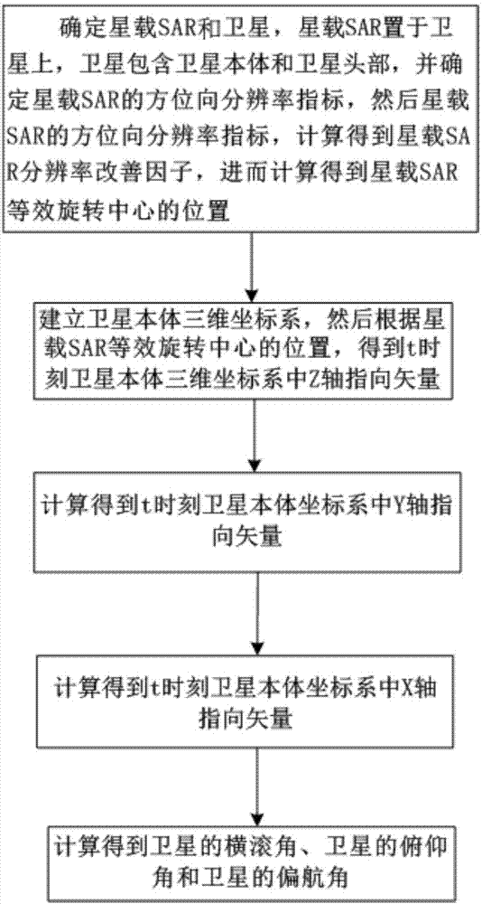
[0027] refer to figure 1 , is a spaceborne SAR sliding spotlight imaging mode star attitude design method of the present invention; wherein the spaceborne SAR sliding spotlight imaging mode star attitude design method comprises the following steps:

[0028] Step 1. Determine the spaceborne SAR, and determine the azimuth resolution index of the spaceborne SAR, and then calculate the improvement factor of the spaceborne SAR resolution according to the azimuth re...


PUM


Abstract

The invention discloses a satellite-borne SAR sliding spotlight imaging mode satellite attitude design method. The main thinking of the satellite-borne SAR sliding spotlight imaging mode satellite attitude design method includes the steps: determining a radar and a satellite; setting the radar on the satellite which includes a satellite body and a satellite head; determining the azimuth resolution index of the radar; according to the azimuth resolution index of the radar, calculating a radar resolution improvement factor so as to calculate the position of a radar equivalent rotation center; establishing a satellite body three dimensional coordinate system XYZ, and according to the position of the radar equivalent rotation center, obtaining the Z-axis directional vector in the satellite body three dimensional coordinate system XYZ at t moment; and calculating the Y-axis directional vector in the satellite body three dimensional coordinate system XYZ at t moment, and calculating the X-axis directional vector in the satellite body three dimensional coordinate system XYZ at t moment so as to calculate the roll angle of the satellite, the pitch angle of the satellite and the yaw angle of the satellite, wherein the roll angle of the satellite, the pitch angle of the satellite and the yaw angle of the satellite are the satellite-borne SAR sliding spotlight imaging mode satellite attitude design result.

Description

technical field [0001] The present invention relates to the technical field of spaceborne synthetic aperture radar detection, in particular to a method for designing the attitude of a star in a spaceborne SAR sliding spotlight imaging mode, which is suitable for the situation where the radar beam cannot be flexibly controlled by phase scanning under the parabolic antenna system , complete the azimuth scanning of the radar beam through the satellite three-axis attitude control. Background technique [0002] Spaceborne synthetic aperture radar SAR is one of the fastest-growing and most effective sensors in microwave remote sensing equipment, and as an active sensor, it can observe the earth all day and all day without being limited by illumination and weather conditions; sliding spotlight imaging mode It is a novel synthetic aperture radar imaging mode, which increases the azimuth coherent accumulation time by controlling the speed of the irradiated area moving on the ground, ...

Claims


Application Information

Patent Timeline
Patent Type & Authority Applications(China)
IPC IPC(8): G01S13/90G06F17/50
CPCG01S13/90G06F30/00G01S13/9052
Inventor 李真芳周超伟王跃锟于海锋张庆君
Owner XIDIAN UNIV
Why Eureka
Try Eureka