
Structured light lighting device and method of producing striped structured light

A structured light illumination and structured light technology, applied in optics, optical components, microscopes, etc., can solve problems such as small illumination field of view, complex optical path structure, and difficult polarization modulation, and achieve the effect of low energy utilization

Active Publication Date: 2017-12-22
SUZHOU INST OF BIOMEDICAL ENG & TECH CHINESE ACADEMY OF SCI
View PDF5 Cites 10 Cited by
  • Summary
  • Abstract
  • Description
  • Claims
  • Application Information

AI Technical Summary

Problems solved by technology

[0004] However, this structured light generation method has the following disadvantages: 1) When the parallel beam passes through the periodic fringe structure, part of the light energy is blocked, which reduces the energy utilization of the system; 2) Only ±1 order light is intercepted to generate interference fringes, but ± The diffraction efficiency of the first-order light is affected by the fringe structure and is lower than 100%, so there is energy loss; 3) It is necessary to design a 4f imaging system and a special filter hole, and the optical path structure is complicated; 4) In order to make the three illumination directions The contrast ratio of the fringe is always 1, and the structured illumination microsystem requires that the illumination light on the sample surface is in the s-polarization state, and the polarization state of the illumination light in the above-mentioned structured light generation scheme does not change with the illumination direction, so it is necessary to Adding polarization modulation devices in the optical path further increases the complexity of the system optical path; 5) Due to the resolution and chip size limitations of Lcos SLM and DMD devices, the diameter of the illumination beam generally cannot exceed 15mm. After passing through the 4f system and the microscopic illumination system The diameter of the illumination area on the sample surface is mostly below 60um, and the field of view is severely limited
To sum up, the existing structured light generation methods have disadvantages such as low energy utilization rate, complex optical structure, difficult polarization modulation, and small illumination field of view.

Method used


Image

  • Structured light lighting device and method of producing striped structured light
  • Structured light lighting device and method of producing striped structured light
  • Structured light lighting device and method of producing striped structured light

Examples


Embodiment 1

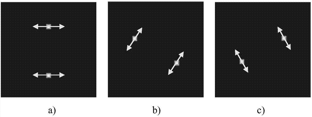
[0032] See figure 1 , figure 1 It is the structured light illumination device provided by the first embodiment of the present invention, which includes: a laser 1, a half-wave plate 2, a condenser lens 4, a beam splitter 5, a reflector 6, an optical path delay module, a Dove prism 9 and a half-wave Plate 10, Dove prism 9 and half-wave plate 10 are rotatably arranged in the optical path; the linearly polarized light emitted by laser 1 sequentially passes through half-wave plate 2 and condenser lens 4, and is divided into reflected beam and transmitted beam by beam splitter 5 light beam; the reflected light beam enters the optical path delay module, and the transmitted light beam is reflected by the mirror 6 to the optical path delay module; the reflected light beam and the transmitted light beam form two illumination beams with the same optical path after passing through the optical path delay module; the two illumination beams After passing through the Dove prism 9 and the ha...


PUM


Abstract

The invention provides a structured light lighting device and a method of producing striped structured light. The structured light lighting device includes a laser, a half-wave plate, a condenser lens, a beam splitter, a reflector, an optical length delay module, and a Dove prism and a half-wave plate which are rotationally arranged in an optical path. Linearly polarized light emitted by the laser passes through the half-wave plate and the condenser lens in sequence, and is then split by the beam splitter into a reflected beam and a transmitted beam. The reflected beam enters the optical length delay module. The transmitted beam is reflected by the reflector to the optical length delay module. After the reflected beam and the transmitted beam pass through the optical length delay module, two lighting beams with the same optical length are formed. After the two lighting beams pass through the Dove prism and the half-wave plate, two spots are generated in a plane P1. A method of producing striped structured light is further provided. With the structured light lighting device adopted, problems such as low energy utilization rate, small lighting field of view and difficult polarization modulation in the prior art are solved.

Description

technical field [0001] The invention relates to the technical field of optical microscopic imaging, in particular to a structured light illumination device and a method for generating striped structured light. Background technique [0002] Optical microscopy imaging technology is a very important technology in the study of biological cells, and it is the main means to study the shape, structure and function of cells. Constrained by the diffraction limit, the highest resolution of existing optical microscopes is generally between 200nm and 400nm. This resolution cannot clearly image some fine structures inside cells. In order to achieve higher resolution of the optical microscopy system, a series of optical super-resolution microscopy techniques have been proposed. [0003] Structured light illumination super-resolution microscopy has the advantages of wide-field imaging, high imaging signal-to-noise ratio, and fast imaging speed. It has great application prospects in the fi...

Claims


Application Information

Patent Timeline
IPC IPC(8): G02B21/00G02B21/06G01N21/21
CPCG01N21/21G02B21/0032G02B21/06
Inventor 唐玉国骆聪巩岩张艳微朗松王宏伟
Owner SUZHOU INST OF BIOMEDICAL ENG & TECH CHINESE ACADEMY OF SCI
Learn More