
Tailstock type vertical takeoff and landing unmanned aerial vehicle and flight control method

A technology for vertical take-off and landing of unmanned aerial vehicles, applied in the field of unmanned aerial vehicles, which can solve the problems of low flight speed, unable to take off and land normally, and low efficiency, and achieve the effects of aircraft safety, increased load, and flight safety

Inactive Publication Date: 2017-12-26
郗杰
View PDF0 Cites 6 Cited by
  • Summary
  • Abstract
  • Description
  • Claims
  • Application Information

AI Technical Summary

Problems solved by technology

At present, the vertical take-off and landing UAVs on the market are generally multi-rotor, flying wing and other layouts, with low flight speed and low efficiency; although fixed-wing UAVs fly fast and have high efficiency, their take-off and landing process The requirements for the environment are particularly high, and a relatively gentle and long-distance takeoff and landing runway is required. It cannot take off and land normally in some venues with harsh environments.

Method used


Image

  • Tailstock type vertical takeoff and landing unmanned aerial vehicle and flight control method
  • Tailstock type vertical takeoff and landing unmanned aerial vehicle and flight control method
  • Tailstock type vertical takeoff and landing unmanned aerial vehicle and flight control method

Examples


specific Embodiment 1

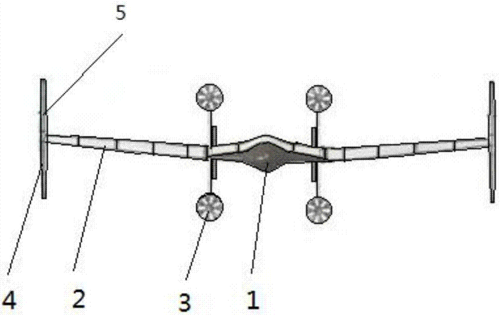
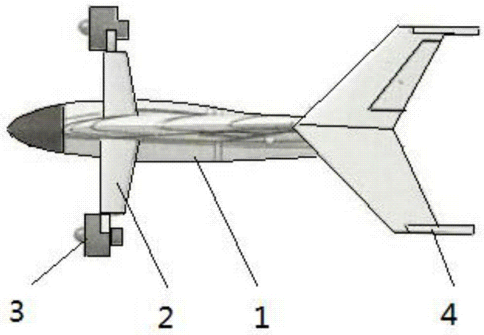
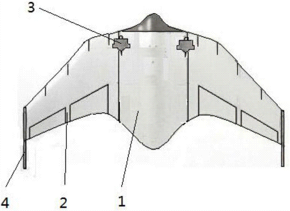
[0037] Refer to the attached Figure 1 to Figure 3 As shown, the present invention provides a tail-sitting vertical take-off and landing unmanned aerial vehicle, comprising wing-shaped fuselage 1, wings 2 on both sides of fuselage 1, four ducted propellers 3 on the upper and lower sides of fuselage 1 and machine The vertical tail 5 above the end of the wing 2 and the wingtip landing gear 4 below, the ducted propeller 3 is driven by a battery or an engine inside the fuselage 1 .

[0038] Further, the fuselage 1 is in the shape of a shuttle, and the width of the end of the connection between the wing 2 and the fuselage 1 is consistent with that of the fuselage 1 . The structure has the characteristics of large lift-to-drag ratio, excellent aerodynamic characteristics, and stable control.

[0039] Refer to the attached Figure 4 As shown, further, avionics equipment 6, said avionics equipment 6 includes GPS or Beidou multi-mode positioning and navigation 61, ultrasonic or optic...

specific Embodiment 2

[0041] According to the control method of any tail-mounted vertical take-off and landing UAV described in the present invention, the flight of the tail-mounted vertical take-off and landing UAV is divided into a take-off section, a take-off transition section, a level flight section, a landing transition section, and a landing section. part;

[0042] Take-off section: refer to the attached Figure 5 As shown, the UAV is set in the four-rotor flight mode, and takes off smoothly in a four-rotor manner through the four ducted propellers 3. At this time, the standard output power of the four ducted propellers 3 is determined according to the load of the UAV. There is no need to establish a speed advantage, hover when taking off to the set height H, and turn to the take-off transition section; the standard output power of the engine is the power when the engine pull is equal to the load of the drone;

[0043]Take-off transition section: refer to the attached Image 6 As shown, th...


PUM


Abstract

The invention relates to a tailstock type vertical takeoff and landing unmanned aerial vehicle and a flight control method. The unmanned aerial vehicle comprises a wing-shaped fuselage, wings, four ducted propellers on upper and lower sides of the fuselage, as well as upper vertical fins and lower wingtip undercarriages at the end parts of the wings, wherein drive force is provided to the ducted propellers by batteries or an engine inside the fuselage. The flight control method of the tailstock type vertical takeoff and landing unmanned aerial vehicle comprise methods in a takeoff stage, a takeoff transition stage, a flat flight stage, a landing transition stage and a landing stage. Quad-rotor and fixed-wing flight modes are both achieved, so the loadability of the vertical takeoff and landing aircraft can be improved; by a unique takeoff and landing manner and layout, flight is smoother and more steady; flat flight speed is quick; the stall problem in takeoff and landing transition stages and a flat flight transition stage is better solved.

Description

technical field [0001] The invention relates to the technical field of unmanned aerial vehicles, in particular to a tail-sitting vertical take-off and landing unmanned aerial vehicle and a flight control method. Background technique [0002] The helicopter platform is complex, the control is difficult, and the flight speed is slow; the multi-rotor platform is simple and easy to control. The appearance of the multi-rotor solves the complicated over-control problem of the helicopter, but the same as the helicopter, the disadvantage is also slow. [0003] However, current rotor or fixed-wing aircraft can solve the speed problem to a certain extent. Taking no Osprey tilt-rotor aircraft as an example, its speed is close to 400 kilometers or hours. However, the technology is relatively complicated. Due to the limitation of the stall speed of level flight from the vertical take-off and landing section to the level flight section, the take-off transition section and the landing tran...

Claims


Application Information

Patent Timeline
Patent Type & Authority Applications(China)
IPC IPC(8): B64C29/00B64C29/02
CPCB64C29/0025B64C29/02B64U10/25B64U30/20B64U50/14
Inventor 郗杰傅大衡
Owner 郗杰
Learn More