
Heat pump drying device

A technology of heat pump drying and heat pump devices, applied in the field of heat pumps, which can solve the problems of narrow adjustable range of condensation temperature, high compressor compression, and high condensation pressure, and achieve the effects of increasing evaporation rate, improving energy efficiency ratio, and high energy efficiency ratio

Active Publication Date: 2017-12-26
西安中亚科技发展有限公司
View PDF9 Cites 5 Cited by
  • Summary
  • Abstract
  • Description
  • Claims
  • Application Information

AI Technical Summary

Problems solved by technology

Existing heat pump dryers use a single refrigerant, the adjustable range of evaporation temperature and condensation temperature is narrow, and the greater the temperature difference between the two, the lower the energy efficiency ratio, which cannot well adapt to various drying requirements
The air volume of the evaporator and condenser of the existing heat pump dryer often adopts the same air volume, and the evaporator needs a large temperature difference in the dehumidification condition to ensure the dehumidification capacity and dehumidification efficiency, so the air volume is small; but the air heat exchange process of the condenser It is sensible heat heating process, small air volume leads to high condensation pressure, high compression ratio of compressor, not energy-saving; and in the drying process of working fluid, higher surface wind speed can increase the evaporation speed of its water and improve dehumidification Drying efficiency, the air volume required by the two is not the same

Method used


Image

  • Heat pump drying device
  • Heat pump drying device
  • Heat pump drying device

Examples


Embodiment Construction

[0039] In order to make the object, technical solution and advantages of the present invention clearer, the present invention will be further described in detail below in conjunction with the accompanying drawings and embodiments. It should be understood that the specific embodiments described here are only used to explain the present invention, not to limit the present invention.

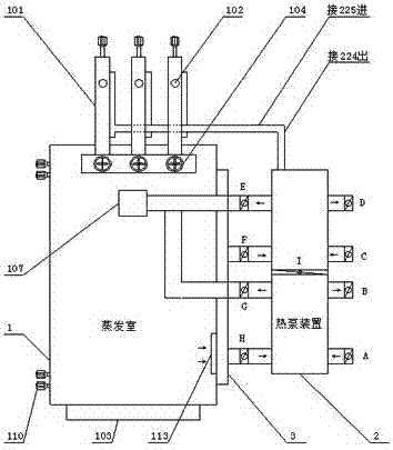
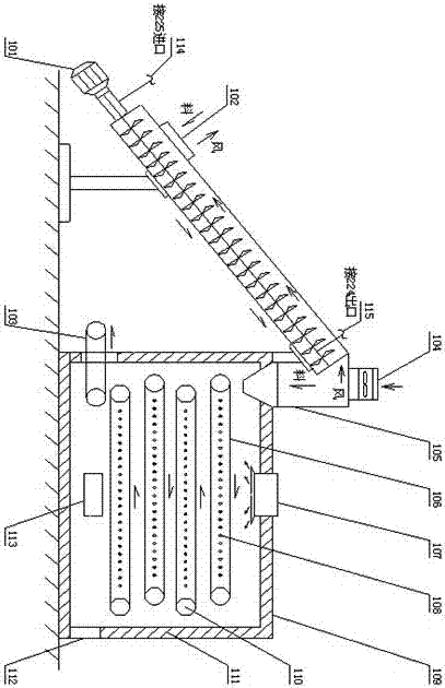
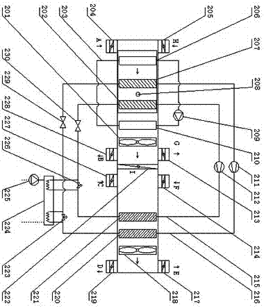
[0040] refer to Figure 1 to Figure 4 ,Such as Figure 1 to Figure 4 The shown heat pump drying device includes an evaporation chamber and a heat pump device; the evaporation chamber includes a main body of the evaporation chamber, a heat preservation structure, a conveying device, an auxiliary drying device, an induced draft fan, an air distribution device, a material distribution device, and a discharge device , Magnetization device;

[0041] The heat pump device includes a high-temperature heat pump cycle, a low-temperature heat pump cycle, an auxiliary heat exchange device, a heat recovery cy...


PUM


Abstract

The invention discloses a heat pump drying device. The heat pump drying device comprises an evaporation room and a heat pump device, wherein the evaporation room comprises an evaporation room main body, a thermal insulation structure, a conveying device, an auxiliary drying device, a draught fan, an air distributing device, a material distributing device, a discharge device and a magnetizing device. According to the heat pump drying device disclosed by the invention, a mode of cooling at one section and heating at one section of the conventional heat pump drying device is changed into a mode of cooling at two sections and heating at two sections, so that high-temperature heat pump cycle has a high energy efficiency ratio under a high-temperature working condition, and low-temperature heat pump cycle has a high energy efficiency ratio under a low-temperature working condition; and the high-temperature heat pump cycle and the low-temperature heat pump cycle are superposed, so that the energy efficiency ratio under the same working condition state is greatly increased in comparison with that of the conventional mode of cooling at one section and heating at one section.

Description

technical field [0001] The invention relates to a heat pump, in particular to a multi-working-condition high-efficiency heat pump drying device. Background technique [0002] At present, the existing heat pump drying device uses the heat pump condenser to heat the circulating air, and then heats the working medium, so that the water in the working medium evaporates, and the circulating air is in a high-temperature and high-humidity state at this time; Cool down and dehumidify, discharge condensed water, the circulating air is in a low-temperature and low-humidity state at this time; then the circulating air is heated by the condenser again, and becomes a high-temperature and low-humidity circulating air, which leads to the evaporation chamber to heat the working medium to take away moisture and achieve the purpose of drying the working medium . Existing heat pump dryers use a single refrigerant, the adjustable range of evaporation temperature and condensation temperature is...

Claims


Application Information

Patent Timeline
IPC IPC(8): F26B21/00F26B25/00F25B30/02F25B41/06F25B41/31
CPCF25B30/02F26B21/001F26B21/004F26B25/00F26B25/002F25B41/31Y02B30/70Y02P70/10
Inventor 姜鉴明
Owner 西安中亚科技发展有限公司
Learn More