A method of making ampere force and electrostatic force driving power machine

A power machine, high-voltage electrostatic technology, applied in teaching models, instruments, educational appliances, etc., can solve the problem of lack of effective realization of electrostatic force and ampere force to jointly drive power machine, etc. Effect

Active Publication Date: 2019-07-16
QIQIHAR UNIVERSITY
View PDF3 Cites 0 Cited by
  • Summary
  • Abstract
  • Description
  • Claims
  • Application Information

AI Technical Summary

Problems solved by technology

Over the years, in order to help students correctly understand this concept and apply electrostatic induction, some demonstration experiments have been set up in conjunction with teaching, such as electrostatic jumping ball experiment, electrostatic pendulum ball experiment, electrostatic roller experiment, electrostatic blower, and the scale static electricity sensor designed by the inventor of this patent. Jumping ball tester, swing electrostatic power machine, etc. Although the existing electrostatic demonstration devices have solved some needs to a certain extent, they lack further development and innovation of electrostatic power demonstration experiments. As power machines, the demonstration power machines currently seen mainly include : Power machines such as heat engines, electric motors (ampere-force driven), standing wave motors, etc., have their unique advantages and limitations. They lack the design and device to effectively realize the joint drive power machines of electrostatic force and ampere force. How to realize the same direction drive of the rotating plate electrostatic moment and ampere moment, this patent will solve this problem

Method used


Image

  • A method of making ampere force and electrostatic force driving power machine
  • A method of making ampere force and electrostatic force driving power machine

Examples


Embodiment Construction

[0016] Taking the high-voltage electrode column N=2 as an example as a further specific implementation description

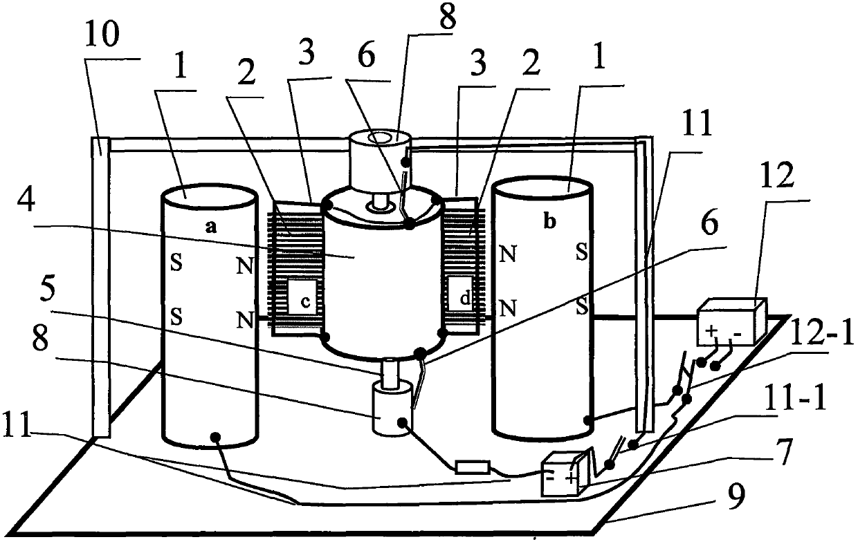
[0017] as attached figure 1 : A method for making ampere force and electrostatic force driven power machine, mainly composed of high voltage electrode column 1, rotating plate 2, ampere force wire 3, plastic cylinder 4, plastic cylinder shaft 5, electric brush 6, ampere force power supply 7, electrode column 8. Composed of high-density insulating board 9, insulating bracket 10, connecting wire 11, amperometric power switch 11-1, high-voltage electrostatic power supply 12, and high-voltage electrostatic power switch 12-1, the feature is that the rotating plate 2 includes a comb-shaped conductor plate c and the comb-shaped conductor plate d are fixed on the busbar of the plastic cylinder 4 (insulating plastic) by a row of copper wires of non-ferromagnetic conductors (the tip facing outward) with one end as the tip, and the plastic cylinder is vertical in the same ...


PUM


Abstract

The invention discloses a method for manufacturing a power machine driven by an Ampere force and an electrostatic force. The power machine is mainly formed by high-voltage electrode columns, a rotation plate, an Ampere force wire, an Ampere force power source, an electrode column, and a high-voltage static power source. The power machine is characterized in that there is an even number N of the high-voltage electrode columns, the rotation plate is formed by an even number N of same comb-like conductor plates, the Ampere force wire is formed by a plurality of enameled wires, the Ampere force wire is fixed on the rotation plate and two ends thereof are fixed on the upper and lower bottom surfaces of a plastic column; and the high-voltage electrode column is manufactured by a columnar permanent magnet magnetized perpendicular to the horizontal direction of an axis, and the cylindrical surface of the columnar permanent magnet is adhered with aluminium-foil paper, so the method of driving the power machine by the electrostatic force and the Ampere force is realized. Such experimental design is good for promoting the creative spirit of students and the practical ability culture. The method is novel and is easily realized, the effect is obvious, more education functions are increased in the teaching process, and the work has the significance and exploitable potential.

Description

technical field [0001] This patent relates to an experimental method for demonstrating ampere force and electrostatic force drive, and belongs to the field of physical experiment instruments. Background technique [0002] In college physics courses, static electricity is an important content, and the application of electrostatic induction is the content that everyone pays attention to. Over the years, in order to help students correctly understand this concept and apply electrostatic induction, some demonstration experiments have been set up in conjunction with teaching, such as electrostatic jumping ball experiment, electrostatic pendulum ball experiment, electrostatic roller experiment, electrostatic blower, and the scale static electricity sensor designed by the inventor of this patent. Jumping ball tester, swing electrostatic power machine, etc. Although the existing electrostatic demonstration devices have solved some needs to a certain extent, they lack further develop...

Claims


Application Information

Patent Timeline
Patent Type & Authority Patents(China)
IPC IPC(8): G09B23/18
CPCG09B23/188
Inventor 梁法库
Owner QIQIHAR UNIVERSITY
Why Eureka
Try Eureka